3
Location Considerations
The proper location to install the water softener system will ensure optimum performance and satisfactory water
quality. The following factors should be considered in selecting the location of the equipment.
1. The water softener should be installed after the pressure tank on a private well system or after the
water meter on municipal water. Operating pressure of the softener must be limited to within 30 –
100 psi range.
2. The water softener should be installed as close as possible (preferably within 15’) to an adequate
floor or laundry drain capable of handling the backwash cycle volume and flow rate (refer to unit
specifications).
3. All water conditioning equipment should be installed prior to the water heater. Water temperatures
exceeding 100°F can damage the internal components of the control valve and filter tank. Install
with at least 10’ of pipe before the water heater to prevent thermal damage to the equipment. An
expansion tank may need to be installed in the line to the water heater in order to allow for thermal
expansion and comply with local plumbing codes.
4. The water softener should not be subject to freezing temperatures.
5. Ensure that any cartridge or in-line type filter installed prior to the water softener does not restrict
the water flow and pressure available for backwash and interfere with normal operation.
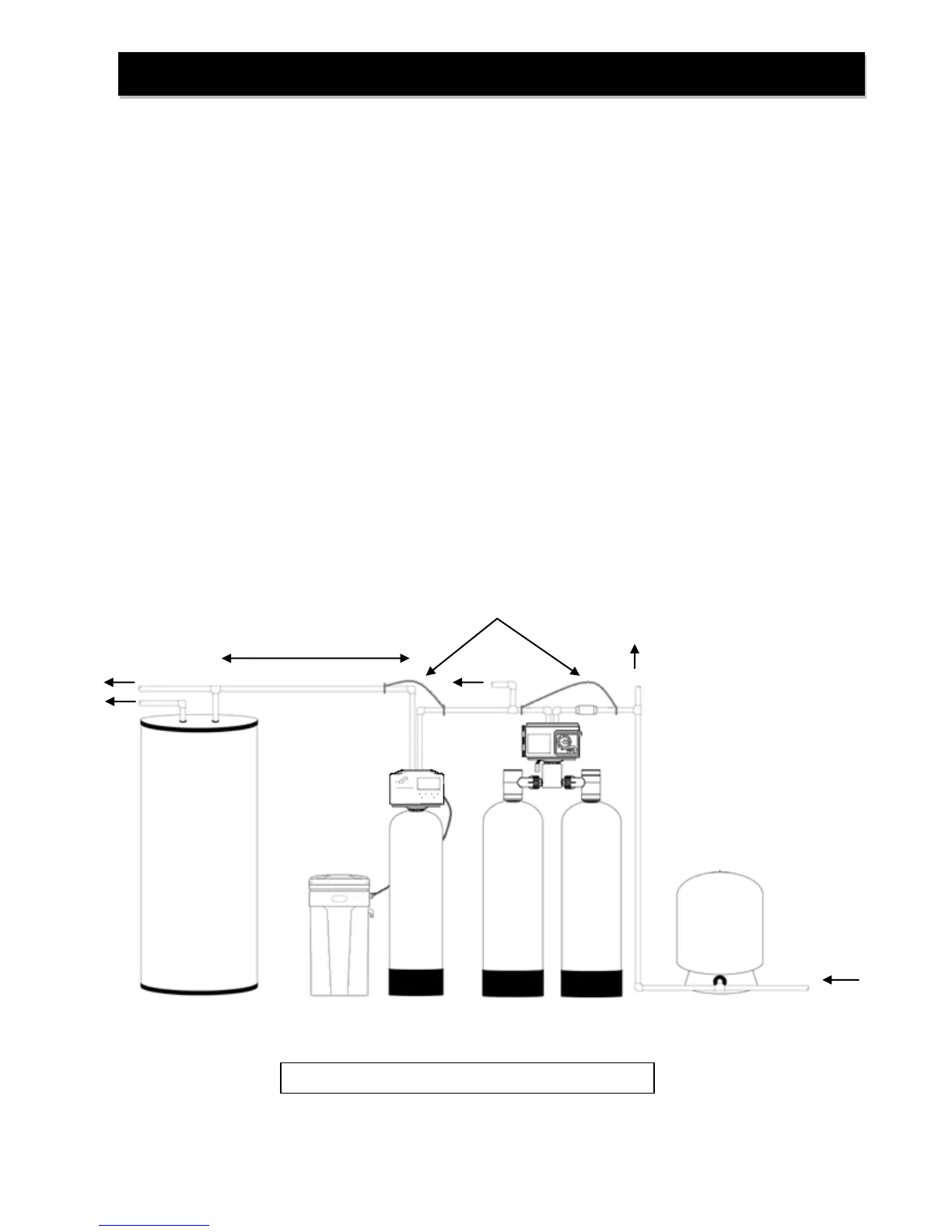
6. Appliances requiring extended periods of continuous or high flow water use (i.e. geothermal heat
pumps, swimming pools, lawn irrigation, outside hose bibs, etc.) should bypass the water softener.
(see installation diagram Fig. 1).
Iron Filter
(if required)
Pressure Tank
(well system only)
Pre-installation Instructions (cont.)
FIGURE 1: Typical Installation