6
STEP 1: Carefully remove all components from packaging. DO NOT DISCARD PACKAGING until all
water softener components and fittings have been located.
STEP 2: Using the coupling nuts, attach bypass valve to the inlet/outlet of the control valve.
STEP 3: Place unit at desired installation position.
STEP 4: Shut off water at main supply. Relieve pressure by opening nearest faucet. On private well
systems, turn off power to pump and drain pressure tank. SHUT OFF POWER OR FUEL
SUPPLY TO WATER HEATER.
STEP 5: Cut main supply line as required to fit plumbing to inlet and outlet of bypass valve. DO NOT
PLUMB INLET AND OUTLET BACKWARDS. Piping should be supported. Do not apply heat
to any fitting attached to the bypass or control valve.
STEP 6: Use the provided polyethylene tubing (NO VINYL TUBING) to run drain line from control valve
discharge fitting to floor drain or sump pit capable of handling the backwash rate of the
softener (refer to specifications and flow rate). DISCHARGE END OF THE DRAIN LINE
MUST BE FIRMLY SECURED! There must be an air gap at the end of the drain line to
prevent siphoning of waste water and meet plumbing code. Total length of drain line should
be 15’ or less. AVOID OVERHEAD DRAINS.
STEP 7: Connect one end of the 3/8” brine line to the control valve quick connect fitting. Insert the other
end of the brine line through the hole in the brine tank and into the quick connect fitting on the
safety brine valve. Remove the quick connect collet retainer clip (if included) before inserting
the brine line into each fitting, press the tube in very firmly and replace the retainer clip behind
the collet. NOTE: THE BRINE TUBING SHOULD BE INSERTED 5/8” INTO THE FITTING.
DO NOT PUT SALT INTO THE BRINE TANK AT THIS TIME.
Detailed Installation Instructions
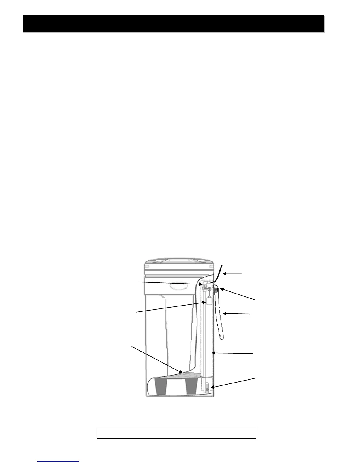
Brine Tank
Overflow Elbow
Brine Overflow
Drain Line
(Not included)
To Floor Drain
Brine Line to Brine
Valve on Control
Valve
FIGURE 3: Brine Tank Components