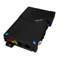
Connector 1 (CN1), 8-Pin Ignition Harness
Pin 1 Red - Constant 12V positive (+) power input. This wire must be connected. The proper vehicle
wire will test (+) 12V at all times - while the key is in the off position, the on position and during
crank.
Pin 2 Green/White – This is the positive (+) parking light wire that triggers when you lock and unlock
the doors and remote start the vehicle.
Pin 3 Red/White - Constant 12V positive (+) power input. This wire must be connected. The proper
vehicle wire will test (+) 12V at all times - while the key is in the off position, the on position and
during crank.
Pin 4 White - Accessory 12V positive (+) output. This wire must be connected to the vehicle accessory
/ HVAC blower motor wire. The proper wire will test 0V with the key in the off position, (+) 12V
while key is in the on position, 0V while cranking and back to (+) 12V when the key is returned to
the on position.
.
Pin 5 Blue - Positive 12V (+) output that powers up during remote start. The behavior of this wire is
selectable by a jumper inside the control module. By default this wire powers up as a 2
nd
Ignition
trigger. It is changeable to a 2
nd
Starter or 2
nd
Accessory.
Pin 6 Yellow - Starter 12V positive (+) output. This wire must be connected for remote start. The proper
wire will test 0V with the key in the off position, 0V while the key is in the on position and (+) 12V
during crank.
Pin 7 Green – Ignition 12V positive (+) output and input. This wire must be connected to the vehicles’
ignition for remote start and valet / remote programming. The proper wire will test 0V with the key
in the off position, 12 V (+) while the key is in the on position and 12V (+) during crank.
Pin 8 Black - Ground negative (-) input. This wire must be connected to the vehicle’s ground.
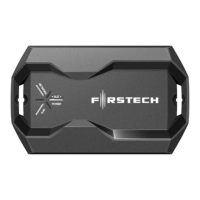
Connector 2 (CN2) Blade Connector and Cartridge
The CM-900 slot gives you the ability to use the Blade-AL and Blade-TB modules from Firstech
and ADS. With these modules you can virtually eliminate all wire connections between your
control module and bypass module. You only need to connect the main ignition harness and
needed from the Black 20 pin Blade connector that may be required according to the vehicle
specific Blade installation guide. For more information on how to program and wire the Blade,
please visit compustar.idatalink.com for the specific wiring diagram for that vehicle.