Pin 11 Red - This wire requires a (+) pulse input for triggering the remote start sequence. This wire
allows you to use the CM-900 as a slave remote starter that can be controlled by a factory OEM
remote.
Pin 12 Yellow/Black - Engine sensing input. This wire is connected to the vehicle’s Tach or Alternator
wire and is required if you are not using the tachless sense setting. IMPORTANT: To change
engine-sensing modes, you must change Option 2-10:
Connector 4 (CN4), 6-Pin (Optional)
Pin 1 Not used
Pin 2 Violet/White - Trunk release 250mA negative (-) output. This is an optional output that will
release the trunk. System will unlock doors and disarm alarm prior to trunk release.
Pin 3 Orange/Black – 2
nd
Pulse Unlock wire. This wire is used to provide the customer with a driver’s
priority unlock feature with option 1-04. With the option on the unlock (blue) wire will pulse first
and then orange/black will pulse if the unlock button is pressed again within 3 seconds.
Pin 4 Blue - Unlock 250mA negative (-) output. This is an optional output that will provide a (-) pulse for
unlocking doors. System will unlock doors. IMPORTANT: You must use relays to reverse
polarity for (+) trigger door lock systems.
Pin 5 Blue/Black - Lock 250mA (-) negative output. This is an optional output that will provide a (-)
pulse for locking doors. System will lock doors. IMPORTANT: You must use relays to reverse
polarity for (+) trigger door lock systems.
Pin 6 Not used
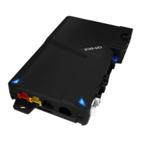
Connector 5 (CN5), 4-Pin (Grey RS232 Port)
This port provides simple connectivity to DroneMobile devices and Fortin bypass modules.
Connector 6 (CN6), 4-Pin (Black RS232 Port)
This port provides simple connectivity to iDatalink bypass modules. This port supports 2-Way iDatalink
protocol.