Do you have a question about the Fischer Panda 8000 NE and is the answer not in the manual?
Comprehensive safety guidelines covering operation, PPE, and hazard avoidance.
Lists essential tools required for maintenance and installation tasks.
Explains important warning labels and safety instructions for generator operation and handling.
Provides 5 critical steps for assisting someone experiencing an electrical shock incident.
Detailed guide on performing rescue breathing and checking pulse for an unresponsive adult.
Defines the generator's purpose and the scope and audience of the user manual.
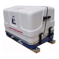
Instructions for safely transporting, loading, and unloading the generator and its accessories.
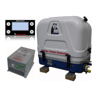
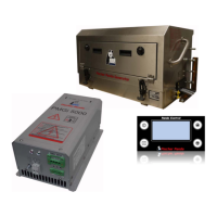
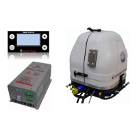
Lists the components included in the generator system package.
Outlines procedures for generator maintenance during periods of extended inactivity or shutdown.
Explains the information provided on the generator's type plate.
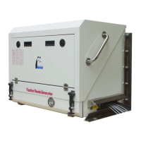
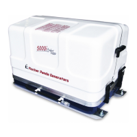
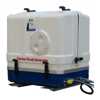
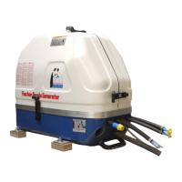
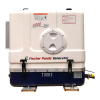
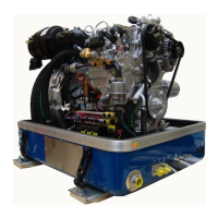
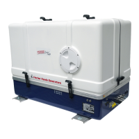
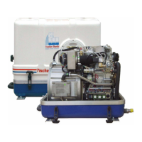
Provides detailed visual descriptions of the generator's left, right, front, back, and top views.
Explains the function of key components like the control panel, cooling, fuel, electrical, and lubrication systems.
Refers to a separate manual for detailed information on the remote control panel.
Outlines personal requirements and critical safety warnings for installing the generator unit.
Guidelines for preparing the installation base and ensuring optimal placement for sound insulation.
Instructions for correctly connecting electrical wires, fuel lines, and cooling water lines.
Procedures for installing both raw water and fresh water cooling systems, including component placement.
Instructions for installing the water-cooled exhaust, fuel supply, and DC electrical systems.
Details on installing the AC control box, voltage control systems, and performing insulation tests.
Covers personal requirements and essential safety precautions before performing any maintenance tasks.
Includes environmental protection, general checks before start, hose/rubber part inspection, and oil change intervals.
Step-by-step guide for draining and replacing engine oil and the oil filter.
Instructions for checking batteries, maintaining grease-lubricated bearings, and replacing oil-cooled bearings.
Covers maintenance of the fuel system's water separator, coolant circuit ventilation, seawater circuit, and impeller wear.
Outlines personal requirements and critical safety warnings before addressing generator faults.
Lists the necessary tools and measuring instruments for diagnosing generator faults.
Provides a detailed list of common generator faults and their potential causes and solutions.
Offers visual flowcharts to guide the troubleshooting process for various generator issues.
Explains how to set the speed governor and troubleshoot low output voltage issues.
Comprehensive tables detailing technical specifications, rated current, cable sizes, fuel, oil, coolant, and coil data.
Explains the function, cleaning, and replacement procedure for the impeller filter.
Lists the part number for the spare kit and provides dimensional drawings for the impeller filter.
Details personal requirements and crucial safety warnings specific to the Generator Control Panel P6+.
Describes the functions and indicators of the Generator Control Panel P6+ interface.
Covers the physical installation, terminal connections, jumper settings, and configuration for remote control panels.
Provides daily checks, step-by-step instructions for starting, and procedures for safely stopping the generator.
Explains the function and connection of automatic and master-slave adapters for extended control.
Provides a dimensional drawing showing the hole pattern layout for the control panel installation.
| Brand | Fischer Panda |
|---|---|
| Model | 8000 NE |
| Category | Portable Generator |
| Language | English |