Do you have a question about the Fischer Panda Panda 8000 and is the answer not in the manual?
General safety instructions and warnings for operation and maintenance.
Lists required tools for maintenance and installation, showing symbols for each tool.
Manufacturer's declaration regarding compliance with CE guidelines and the Machinery Directive.
Benefits of product registration and details on technical support and startup.
Detailed safety instructions covering operation, PPE, cleanliness, and handling of fuels.
Guidelines for keeping warning and instruction signs clean and legible.
Steps for providing rescue breathing to an adult.
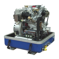
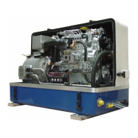
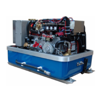
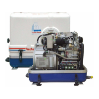
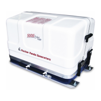
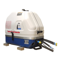
Describes the primary function of the Fischer Panda generator.
Explains the manual's purpose and defines roles of personnel involved with the generator.
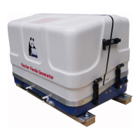
Lists the standard components included with the Fischer Panda generator system.
Instructions for opening the Panda transport box.
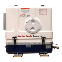
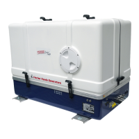
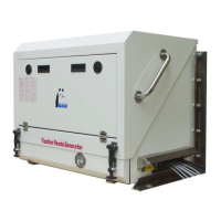
Procedure for opening the MPL sound insulation capsule.
Guidelines for safely transporting and loading/unloading the generator.
Procedures for extended downtimes and decommissioning.
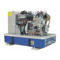
Provides a description of the genset, including views and component identification.
Details various functional units of the generator, including the control panel.
Specifies that installation must be performed by trained personnel.
Provides guidance on the environmentally sound disposal of motor fluids and batteries.
Details requirements for the installation location and foundation.
Discusses the air intake filter as a source of noise and potential solutions.
Describes electrical connections and points on the generator.
Provides instructions for installing the fuel system.
Instructions on how to vent the fuel system.
Instructions for installing the cooling system and its components.
Guidance on designing the radiator foundation based on application.
Discusses special installations and their impact on warranty.
Provides installation schematics for various radiator mounting configurations.
Instructions for exhaust system installation.
Details electrical connections for various components.
Instructions for installing the DC system components.
Instructions for connecting the AC network and AC control box.
Recommendation for installing a voltage monitor for protection.
Overview of fan control and regulation options.
Description of the standard single-phase and three-phase fan control.
Details on the RE0201 fan control for DC fans.
Information on electronic speed control for single-phase fans.
Information on electronic speed control for single-phase fans.
Information on electronic speed control for three-phase fans.
Procedure for performing an electrical isolation test before commissioning.
Instructions for commissioning the generator after installation.
Specifies that only authorized and instructed personnel may operate the generator.
Highlights safety warnings relevant to generator operation.
General operating instructions, including low-temperature operation.
Pre-start checks referencing the remote control panel datasheet.
Procedure for starting the generator as per the remote control panel datasheet.
Procedure for stopping the generator as per the remote control panel datasheet.
Instructions for starting the generator with an overheat error using the bypass switch.
Specifies who can perform maintenance tasks.
Highlights safety warnings specific to maintenance work.
Provides an overview of maintenance intervals and checks.
Guidance on the proper disposal of motor fluids.
Special maintenance for long downtimes and decommissioning.
Instructions and intervals for changing engine oil and oil filters.
Procedure for checking and refilling engine oil.
Step-by-step guide for changing engine oil and the oil filter.
Instructions for checking the starter battery and battery bank.
Procedure for bleeding the cooling water system.
Instructions for replacing the air filter.
Procedure for venting the fuel system.
Instructions for replacing the optional oil pressure sensor.
Instructions for replacing the oil pressure switch.
Instructions for replacing the actuator motor.
Instructions for replacing the starter motor.
Instructions for replacing the DC alternator.
Instructions for replacing the work current relays.
Instructions for replacing fuses.
Instructions for replacing thermoswitches.
Instructions for replacing the V-belt for the internal cooling water pump.
Instructions for replacing the injection nozzles.
Instructions for replacing the glow plugs.
Instructions for replacing the stop magnet (optional).
Instructions for replacing the valve cover gasket.
Procedure for adjusting valve clearance.
Instructions for replacing the water pump.
Information on grease-lubricated generator back end bearings.
Procedure for checking the oil level in the generator end bearing.
Instructions for replacing the oil-cooled back end bearing.
Specifies personnel authorized for repair work.
Highlights safety warnings relevant to troubleshooting.
Lists tools and measuring instruments required for troubleshooting.
Flowchart for diagnosing and identifying errors.
Troubleshooting table listing causes and remedies for common generator issues.
Instructions for setting the nominal charging current.
Information on generator overload, including behavior during short circuit and overload.
Troubleshooting steps for low generator output voltage.
Troubleshooting steps for low generator output voltage.
Guidance for diagnosing and resolving engine start problems.
Table of winding resistance and inductance values.
Table specifying required cable cross-sections based on length and current.
Technical specifications for various Panda generator models.
Information on engine oil classification and quality.
Information on coolant mixture and recommended products.
Specifications for the required diesel fuel.
Manual for the 12V version of the Generator Control Panel P6+.
Manual for the 24V special version of the Generator Control Panel P6+.
Details on the automatic adapter option for the Generator Control Panel P6+.
Details on the master-slave adapter option for the Generator Control Panel P6+.
Specifies requirements for personnel performing settings or installations.
General safety instructions for operating the generator control panel.
Overview of the generator control panel front view and its indicators.
Details of the rear view of the 24V version control panel.
Instructions for installing the remote control panel.
Daily checks required before starting the generator for marine and vehicle versions.
Procedures for starting and stopping the generator.
Functionality and operation of the automatic adapter.
Details on connecting Master-Slave adapters.
Provides the hole pattern layout for the generator control panel.
| Model | Panda 8000 |
|---|---|
| Type | Portable Generator |
| Power Output | 6.4 kW |
| AC Output | 230V |
| Voltage | 230V |
| Frequency | 50 Hz |
| Engine | Kubota Z482 |
| Fuel | Diesel |
| Cooling | Water-cooled |
| Start System | Electric Start |
| Noise Level | 52 dB(A) at 7m |