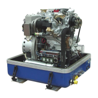
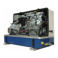
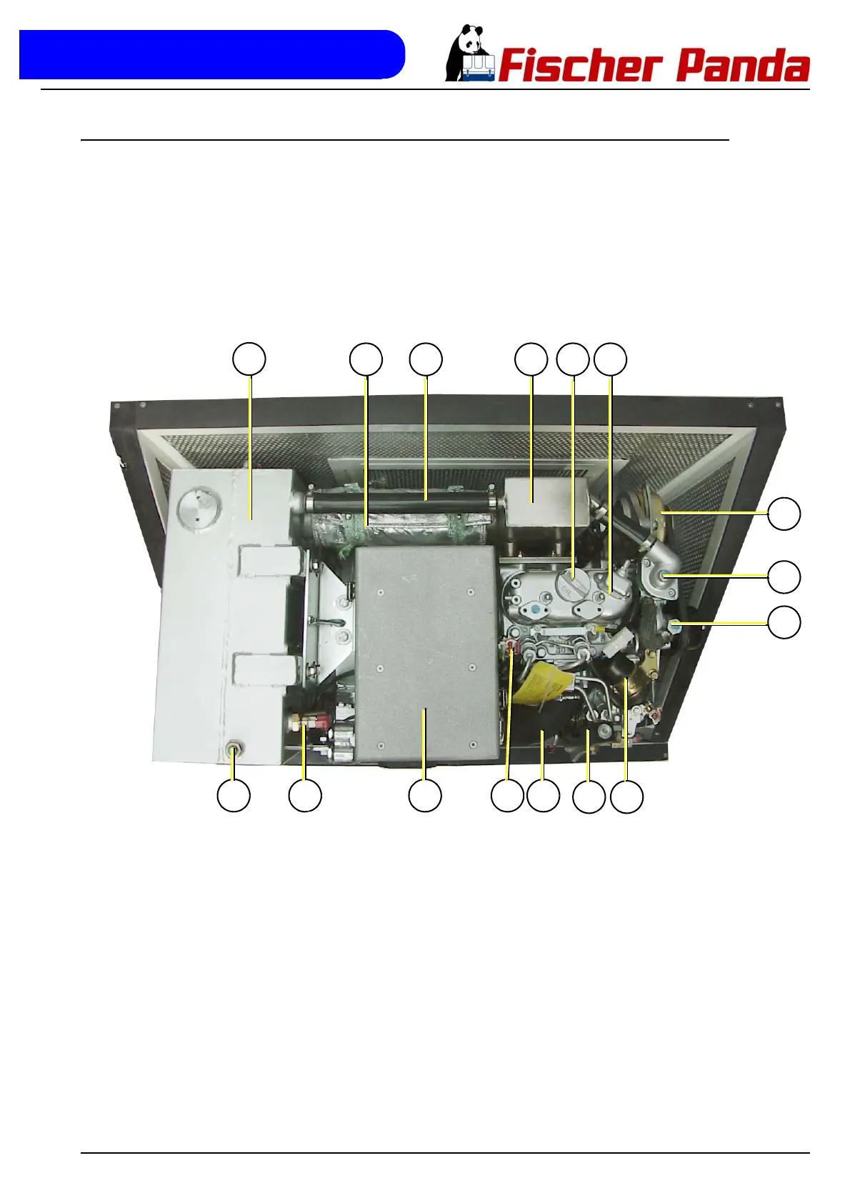
Fig. A.1.5-1: View from above
01. Water-cooled pre-silencer
02. Compensator under heat isolation
03. Cooling water hose
04. Water-cooled exhaust manifold
05. Oil filler neck
06. Cylinder head
07. DC-alternator 12V
08. De-aerating screw at the thermostat housing
09. De-aerating screw at the internal cooling water pump
10. Stop solenoid
11. Fuel solenoid valve
12. Air suction tube, housing - induction elbow
13. Thermo-switch at the cylinder head
14. Air suction housing with air filter
15. Thermo-switch at the silencer
16. De-aerating screw at the silencer