Do you have a question about the Fisher & Paykel GC9002QJET and is the answer not in the manual?
| Category | Cooktop |
|---|---|
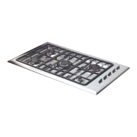
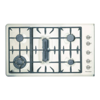
| Type | Gas Cooktop |
| Number of Burners | 5 |
| Width | 90 cm |
| Finish | Stainless Steel |
| Safety Features | Flame failure protection |
| Auxiliary Burner Output | 3.5 MJ/h |
| Ignition Type | Electronic |
| Material | Stainless Steel |
| Fuel Type | Natural Gas / LPG |
| Burner Types | Auxiliary, Semi-Rapid |
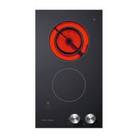
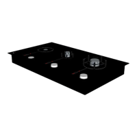
Details physical dimensions for GC600, GC900, and GC9002/GC36 series cooktops.
Explains the coding system used for Fisher & Paykel cooktop model names.
Specifies the required dimensions for installing cooktops into benches or countertops.
Lists burner types, gas ratings (MJ/h, kW, BTU), and orifice sizes for different regions.
Details the number and type of gas valves and flame failure valves used per model series.
Provides specifications for mains powered ignition systems and associated part numbers.
Presents total gas consumption figures for various cooktop models and gas types.
Stipulates that gas products must only be installed by qualified service personnel.
Illustrates the ignition circuit schematic for GC600, GC900, and GC9002 series gas cooktops.
Depicts the ignition circuit schematic specifically for the GC36 gas cooktop in the USA/Canada.
Instructions on how to check and adjust the minimum flame setting on burners.
Procedure for changing gas injector orifices and gas pressure for different gas types.
Step-by-step guide on how to safely remove the cooktop's hob assembly.
Instructions for disconnecting and removing the entire cooktop unit from its installed location.
Procedure for safely replacing a faulty ignition electrode on the cooktop.
Steps to replace the electronic ignition control box, including electrode connections.
Guide for replacing the microswitch wiring harness on specific cooktop models.
Method for testing the functionality of the flame failure safety device.
Instructions for removing and replacing the thermocouple component.
Detailed steps for the removal and replacement of a gas valve.
Procedure for cleaning and re-greasing gas valves for proper operation.
Troubleshooting steps for cooktops that do not ignite and show no spark.
Diagnosing ignition problems when a spark is present but the gas does not ignite.
Troubleshooting why the flame extinguishes after the control knob is released.
Method for testing the output of the thermocouple using a multimeter.
Troubleshooting no spark issues during the auto-reignition process.
Diagnosing ignition failure when spark is present but flame does not establish.
Steps to resolve issues where the igniter sparks continuously after ignition.
Procedure to identify specific burners causing continuous sparking problems.
Troubleshooting why the flame extinguishes when the burner is set to its low setting.
Diagnosing and rectifying issues with distorted, large, or yellow flames.