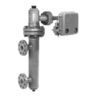
2502 Series
18
Table
3. Troubleshooting Chart for 2502 Series Controllers
Fault Possible Cause Check Correction
1. Process wanders or cycles
around setpoint.
1.1 Proportional band or specific
gravity adjsutment incorrect or
improperly tuned control loop.
1.1 Insure the prestartup
procedures are completed
correctly. Tune control loop.
1.1 If stable control cannot be
attained and all other elements are
functionally correct, examine other
ossible causes related to the
controller/transmitter.
1.2 Supply pressure varying or
incorrect supply pressure setting.
1.2 Use input pressure gauge to
monitor stability. Make sure
regulator IN supply pressure is
withlin limits.
1.2 Apply correct supply pressure.
It is recommended to use one
regulator per instrument.
1.3 Sensor not plumb and is in
contact with sidewall or leak in
displacer.
1.3 Check cage vessel and stillwell
installation, or for leaking displacer.
1.3 Make sure the displacer and
displacer rod hangs freely. Make
sure linkage is tight. Replace
displacer if leaking.
1.4 Relay malfunction. 1.4 Check for relay malfunction by
using the testing relay deadband
procedure
1.4 Depress plunger to clean out
the fixed restriction. Replace or
repair relay using the procedure in
the Maintenance section.
2. Controller controlling off setpoint
or switching point.
2.1 Supply pressure not set
correctly.
2.1 Make sure regulator supply
pressure is set correctly. Make sure
regulator IN supply pressure is
within limits.
2.1 Reset the supply regulator
pressure. If the condition occurs
again, rebuilld or replace regulator.
Provide a regulator input pressure
within regulator limits.
2.2 Leak in the controller loop. 2.2 Use soap and water to check
for internal and external leaks.
2.2 Replace or repair leaking parts
as necessary.
2.3 Leaking displacer. 2.3 Insure the displacer is not filling
with process fluid.
2.3 Refer to sensor maintenance
procedures in the appropriate
sensor instruction manual.
2.4 Flapper adjustment. 2.4 Insure the flapper is not loose
on the torque tube shaft and is
centered on the nozzle.
2.4 Replace or tighten flapper
assembly as necessary and/or
center flapper on nozzle.
2.5 Process variable changed. 2.5 Insure the process variable has
not changed from original
calibration settings or, displacer not
design specific gravity of process.
2.5 Change process variable back
to original sepcification or
recalibrate. If necessary, provide
replacement displacer of correct
size and recalibrate.
3. Controller cannot attain full
output range.
3.1 Supply pressure not set
correctly.
3.1 Make sure supply pressure is
set correctly. Make sure regulator
IN supply pressure is within limits.
3.1 Reset the regulator pressure. If
problem reoccurs, replace or
rebuild the regulator. Insure
regulator IN supply pressure is
within limits at all operating levels.
3.2 Flapper adjustment. 3.2 Insure the flapper is not loose
on the torque tube shaft and is
centered on the nozzle.
3.2 Replace or tighten flapper
assembly as necessary and/or
center flapper on nozzle.
3.3 Process variable changed. 3.3 Insure the process variable has
not changed from original
calibration settings or, from
displacer design specific gravity.
3.3 Change process variable back
to original specificaton or
recalibrate. If necessary, provide
replacement displacer of correct
size and recalibrate.
3.4 Relay malfunction. 3.4 Check for relay malfunction by
using the testing relay deadband
procedure.
3.4 Depress plunger to clean out
the fixed restriction. Replace or
repair relay using the procedure in
the Maintenance section.
3.5 Leaking controller loop. 3.5 Use soap and water to check
for internal and external leaks.
3.5 Replace or repair leaking parts
as necessary.
4. Controller remains at full or zero
output pressure.
4.1 Supply or output pressure
gauge malfunction
4.1 Insure the pressure gauges are
registering correctly.
4.1 Replace pressure gauges. Use
corrective action given in section 3
of this table.
4.2 Flapper adjustment. 4.2 Insure the flapper is not loose
on the torque tube shaft. Insure the
flapper is centered on the nozzle.
4.2 Replace or tighten flapper
assembly as necesary and/or
center flapper on nozzle.
Perform step 1 only if adding a heat insulator to a
unit that does not have one. Key numbers in this
step are shown in figure 14.
1. To install the heat insulator, secure the shaft exten-
sion (key 37) to the torque tube assembly rotary shaft
with the shaft coupling (key 36). Tighten both set
screws (key 38), with the coupling centered as shown
 Loading...
