2502 Series
19
Figure
14. Heat Insulator Shown Installed on 249 Series
20A7423-C/DOC
in the figure. Then mount the insulator assembly (key
35) on the controller case with four washers (key 53)
and button-head cap screws (key 40). Tighten the
screws.
CAUTION
In the following step, avoid bending the
torque tube rotary shaft of the torque
tube assembly. Bending or side loading
of this shaft could cause erroneous
readings. Additionally, make sure the
ball bearing assembly (key 12, figure 16)
is removed from the case (key 1, figure
16) to provide clearance when installing
the case on the sensor.
2. Remove the bearing assembly (key 12) from the
case (key 1).
3. Carefully slide the controller case straight in, guid-
ing the bearing assembly (key 12), operating arm base
or pointer assembly (key 68 or 51, figure 16) over the
rotary shaft and easing an attached heat insulator over
the shaft coupling (key 36, figure 14) if necessary. Se-
cure the case or insulator to the torque tube arm with
the four cap screws (key 39, figure 14).
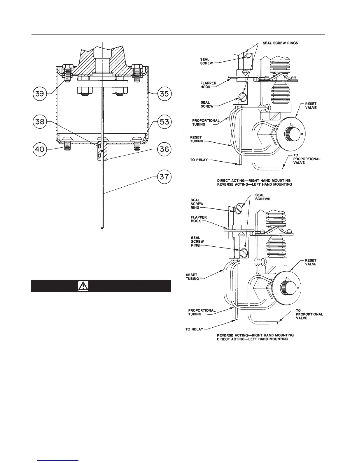
Figure
15. Nozzle, Flapper, and Tubing Arrangements
for Various Actions and Mountings
AV2323-A
AV2322-A
B0995-2/IL
Note
If a heat insulator is used, do not insu-
late its exterior.
4. On a unit without a heat insulator, tape the joint
between the case and torque tube arm to minimize the
entrance of atmospheric moisture around the torque
tube rotary shaft.

 Loading...


