Instruction Manual
D200129X012
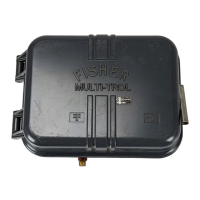
2506/2516 Receiver/Controller
June 2017
3
Table 1. Specifications
Available Configurations
For additional information, refer to table 2
2506: A receiver/controller
(1)
that is set for either
proportional or snap action (S) control or for either
direct or reverse (R) action
2516: A 2506 that also provides proportional‐plus-
reset control
2516F: A 2516 that also provides anti‐reset windup
control
Input Signal Range
From a transmitter or control device, a signal of 0.2 to
1.0 bar (3 to 15 psig) or 0.4 to 2.0 bar (6 to 30 psig) is
required depending on receiver/controller range
Refer to the receiver/controller nameplate for specific
range.
Output Signal Range
(2)
See table 3
Output Action
Direct Action: An increasing fluid, interface level, or
density increases output pressure or,
Reverse Action: An increasing fluid, interface level, or
density decreases output pressure
Remote Set Point Signal Range
From a control device, provide a remote set point
signal that is 0.2 to 1.0 bar (3 to 15 psig) or 0.4 to 2.0
bar (6 to 30 psig) that matches the receiver/controller
input signal range
Supply Pressure
(3)
Normal Operating Pressure: See table 3
Maximum Pressure to Prevent Internal Part Rupture:
3.4 bar (50 psig)
Supply Medium
Air or Natural Gas
Supply medium must be clean, dry, and noncorrosive
Per ISA Standard 7.0.01
A maximum 40 micrometer particle size in the air
system is acceptable. Further filtration down to 5
micrometer particle size is recommended. Lubricant
content is not to exceed 1 ppm weight (w/w) or
volume (v/v) basis. Condensation in the air supply
should be minimized
Per ISO 8573-1
Maximum particle density size: Class 7
Oil content: Class 3
Pressure Dew Point: Class 3 or at least 10_C less than
the lowest ambient temperature expected
Steady State Air Consumption
(2)
See table 3
Proportional Band Reset, and Anti‐Reset Windup
See table 2 and the Changing Controller Action
procedure
Performance
Hysteresis: 0.6 percent of output pressure change at
100 percent of proportional band for 2506
proportional receiver/controllers only
Standard Supply and Output Pressure Gauge
Indications
See table 3
Standard Tubing Connections
All connections are 1/4 NPT internal
Hazardous Area Classification
2506 receiver/controllers comply with the
requirements of ATEX Group II Category 2 Gas and
Dust
Operative Ambient Temperature Limits
(3)
Standard: -40 to 71°C (-40 to 160°F)
High Temperature: -18 to 104°C (0 to 220°F)
-continued-

 Loading...