Instruction Manual
D200129X012
2506/2516 Receiver/Controller
June 2017
2
Introduction
Scope of Manual
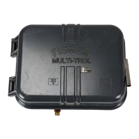
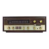
This manual provides installation, startup, calibration, maintenance, and parts ordering information for 2506 and
2516 receiver/controllers. Figure 1 shows a 2506 receiver/controller. Figure 2 shows a 2516 receiver/controller.
A 2506/2516 receiver/controller is often used with a 2502 controller/transmitter. For information about 2502
controller/transmitters or associated equipment such as pressure regulators, sensors, accessories, or related control
devices, see the appropriate instruction manual, or contact your Emerson sales office
or Local Business Partner.
Do not install, operate, or maintain a 2506/2516 receiver/controller without being fully trained and qualified in valve,
actuator, and accessory installation, operation, and maintenance. To avoid personal injury or property damage, it is
important to carefully read, understand, and follow all contents of this quick start guide, including all safety cautions
and warnings. If you have any questions about these instructions, contact your Emerson sales office or Local Business
Partner before proceeding.
Description
See table 2.
The receiver/controllers described in this manual provide:
D Proportional‐only control: 2506 (with snap action: 2506S)
D Proportional‐plus‐reset control (2516)
D Proportional‐plus‐reset‐plus‐anti‐reset windup control (2516F)
See figures 9, 10, and 11.
The receiver/controller takes a pneumatic input signal from either a 2500 controller/transmitter or a control device.
The unit then provides a pneumatic output signal that operates a final control element.
When a 2506 receiver/controller is used to provide proportional‐only control, the pneumatic output signal from the
unit can also be piped to a remote receiving indicator or recording device. This provides a visual indication of
receiver/controller action.
The INCREASE OUTPUT PRESSURE adjustment is used to increase or decrease the output pressure in relationship to the
input pressure. Changing this adjustment changes the position of the nozzle in relationship to the beam/flapper
assembly. In turn, the amount of supply pressure released by the relay is changed and the pneumatic output signal
that operates a final control element is affected.
If a remote set point signal is used, it is piped to the remote set point connection and into remote set point bellows.
The remote signal expands the bellows and moves the beam/flapper assembly. This affects the controller output in the
same way a change in the INCREASE OUTPUT PRESSURE adjustment affects the output.
Specifications
Specifications are shown in table 1.
 Loading...