Instruction Manual
D200129X012
2506/2516 Receiver/Controller
June 2017
5
Installation
WARNING
To avoid personal injury or property damage resulting from the sudden release of pressure:
D Always wear protective clothing, gloves, and eyewear when performing any installation procedures to avoid personal
injury.
D Check with your process or safety engineer for any additional measures that must be taken to protect against process
media.
D If installing into an existing application, also refer to the WARNING at the beginning of the Maintenance section in this
instruction manual.
CAUTION
Do not use sealing tape on pneumatic connections. This instrument contains small passages that may become obstructed
by detached sealing tape. Thread sealant paste should be used to seal and lubricate pneumatic threaded connections.
Mounting the Controller
Note
If a separate receiver/controller unit has been ordered for field installation with an existing valve/actuator assembly or 2500
controller/transmitter, additional mounting parts may be required. Find the mounting description in the parts list at the end of this
manual. Then, order any additional parts.
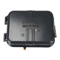
Figures 3 through 8 show dimensions and connection locations used when you install a receiver/controller.
Figure 3. Dimensions and Location of Connections
AD4913‐H
A3844‐1
235
(9.25)
232
(9.12)
171
(6.76)
44
(1.75)
70
(2.75)
70
(2.75)
57
(2.25)
41
(1.62)
mm
(INCH)
BELLOWS VENT OR
REMOTE SET POINT
CONNECTION
OUTPUT CONNECTION
(MARKED DIAPHRAGM)
SUPPLY
CONNECTION
INSTRUMENT
CONNECTION
MOUNTING
HOLES (2 PLACES)
5/16‐18 UNC
TAPPED
VENT FOR
VENT LINE
(OPTIONAL)
CASE VENT
REAR VIEW
BOTTOM VIEW
FRONT VIEW
 Loading...