3570 Series
14
6. Rotate the cable spool to obtain the correct initial
range spring extension. Each full revolution of the
spool extends the range spring 2 inches (50.8 mm)
[1/4-inch (6.4 mm) for 1/8 revolution]. If the initial
range spring extension is not specified, calculate it
using one of the equations given below. Round off the
amount of extension (e) obtained from the equation to
the next higher 1/4 inch (6.4 mm).
T
1.87 (P
n
)
(standard bellows)
e=
T
1.25 (P
n
)
(optional high pressure bellows)
e=
where:
e = initial range spring extension required in inches
T = actuator travel in inches
P
n
= input signal span in psi (for example, 12 psi for
a 3 to 15 psig input signal range)
or
where:
e = initial range spring extension required in mm
T = actuator travel in mm
P
n
= input signal span in bar (for example, 0.8 bar for
a 0.2 to 1 bar input signal range)
7. If necessary, move the actuator cable ball to the
spool slot nearer the access opening. With the actua-
tor piston rod fully retracted and the range spring at
the correct initial extension, attach the cable strap to
the actuator feedback arm. Use the set of cable strap
holes that is closest to the tapped holes in the feed-
back arm.
8. Refer to the positioner adjustment procedures.
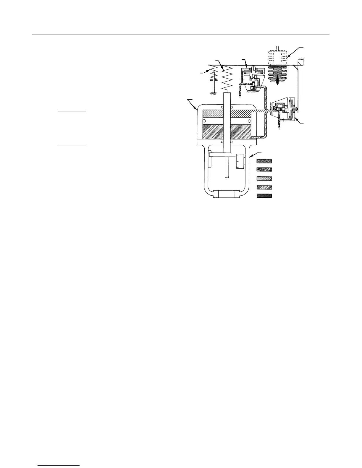
Principle of Operation
Type 3570, 3570C, 3570P, 3570PC, and
3571 Valve Positioners
Refer to the schematic diagram in figure 7. The pneu-
matic output signal from a control device is piped to
the positioner bellows. For explanation purposes, as-
sume this signal has increased. The bellows expands
and moves the beam, which pivots around a fixed
point and simultaneously uncovers the nozzle of relay
B and covers the nozzle of relay A. The nozzle pres-
Figure 7. Schematic Diagram of T
ype 3570 Positioner with a
470 Series Pneumatic Piston Actuator
BOTTOM CYLINDER PRESSURE
NOZZLE PRESSURE
TOP CYLINDER PRESSURE
SUPPLY PRESSURE
INPUT SIGNAL PRESSURE
YOKE
RELAY “A’’
BELLOWS
REVERSED
POSITION
RELAY “B’’
RANGE SPRING
CYLINDER
R = RESTRICTION
A1067-1 / IL
BIAS
SPRING
SUPPLY
R
INPUT
SIGNAL
R
SUPPLY
sure in relay A increases due to the restriction created
by the beam covering the nozzle. Through relay ac-
tion, the pressure to the top of the piston increases. At
the same time, relay B reacts to the change in beam
position to decrease the pressure to the underside of
the piston. These unbalanced pressures move the ac-
tuator piston down.
In the Type 3570 and 3570C positioners, the piston
movement is fed back to the beam by means of a
range spring, which is connected to the beam and to
the piston rod extension. In the Type 3570P, 3570PC,
and 3571 positioners, the feedback is provided to the
range spring by a cable or wire that is connected to
the actuator-valve stem connector. The downward
movement of the piston rod extension extends the
range spring until the torque on the beam balances the
torque exerted by the instrument bellows.
As the input signal decreases, the reverse action
takes place. The bellows contracts, and as the beam
pivots, it covers the nozzle of relay B and uncovers the
nozzle of relay A. Through relay action, the pressure
below the piston increases and the pressure above the
piston decreases to move the piston upward.
Type 3572 and 3576 Valve Positioners
Refer to the schematic diagram in figure 8, which
shows the Type 3572 positioner mounted on a Fisher
 Loading...