3570 Series
12
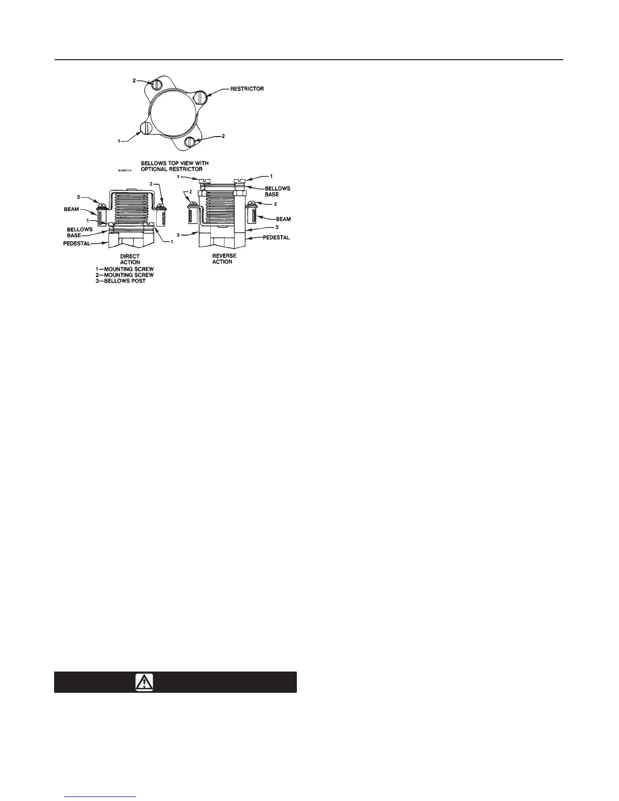
Figure 6. Bellows Mounting for Direct and Reverse Action
A1088-1/IL
expected range with an input signal less than the high
value of the input signal range, decrease the travel by
adjusting the range spring clockwise.
9. Repeat steps 7 and 8 until the valve plug or travel
indicator action corresponds to the input signal re-
quirements of the application [3 to 15 psig (0.2 to 1.0
bar) in this example].
10. Lock the range spring and the bias spring seat in
position. The positioner is then ready for operation.
11. If the positioner is unstable and adjustment does
not correct the problem, it might be due to unwanted
fluctuations in the input signal. A restrictor assembly
(key 47, figure 11) can be installed in the input signal
circuit to dampen these fluctuations. The restrictor
might help to minimize instability. To take the restrictor
out of service, exchange the location of the restrictor
with that of the bellows mounting screw (key 46, figure
11).
12. Replace the cover (key 39) on the positioner.
Changing Positioner Action
The instructions given below are to be used after the
springs have been changed or if no spring change is
required. Numbered parts mentioned in this section
are shown in figure 6 unless otherwise noted.
WARNING
The following procedures require taking
the positioner, actuator, and control
valve assembly out of service. To avoid
personal injury or property damage
caused by uncontrolled process pres-
sure, provide a temporary means of con-
trol for the process before taking the as-
sembly out of service.
Before removing the input signal and
supply pressure connections from the
positioner, remove the input signal and
supply pressure sources from the
connections. The sudden release of
pressure can cause personal injury or
property damage.
Note
Changing the positioner action might
require changing the bias spring and/or
the spring retainer. Refer to table 4 for
correct signal range codes. Refer to the
Maintenance section for disassembly
and assembly procedures.
Changing to Reverse Action
1. Bypass the control valve and shut off the input sig-
nal line and the supply pressure line to the positioner.
2. Loosen the four thumb screws on the underside of
the positioner base and remove the cover.
3. Two bellows posts are provided. The posts are
screwed into storage holes in the positioner base im-
mediately above the CYLINDER and INSTRUMENT
connections. Unscrew these posts.
Note
An optional restrictor (see the top view
in figure 6) can be found in place of one
of the bellows mounting screws (num-
ber 1). If so, note the location of the re-
strictor and replace it in the same loca-
tion during reassembly. The restrictor
has a hex head; the mounting screws do
not.
4. Remove the four mounting screws (numbers 1 and
2) and lift out the bellows assembly.
5. Screw the bellows posts (number 3) into the holes
where the screws (number 1) originally were.
6. Invert the bellows and replace the screws (num-
bers 1 and 2).
7. Refer to the adjustment procedures to check op-
eration of the positioner.
8. Make a notation on the action label (key 43, figure
11) that the action of the positioner has been changed.
9. Replace the cover (key 39) on the positioner.