3570 Series
16
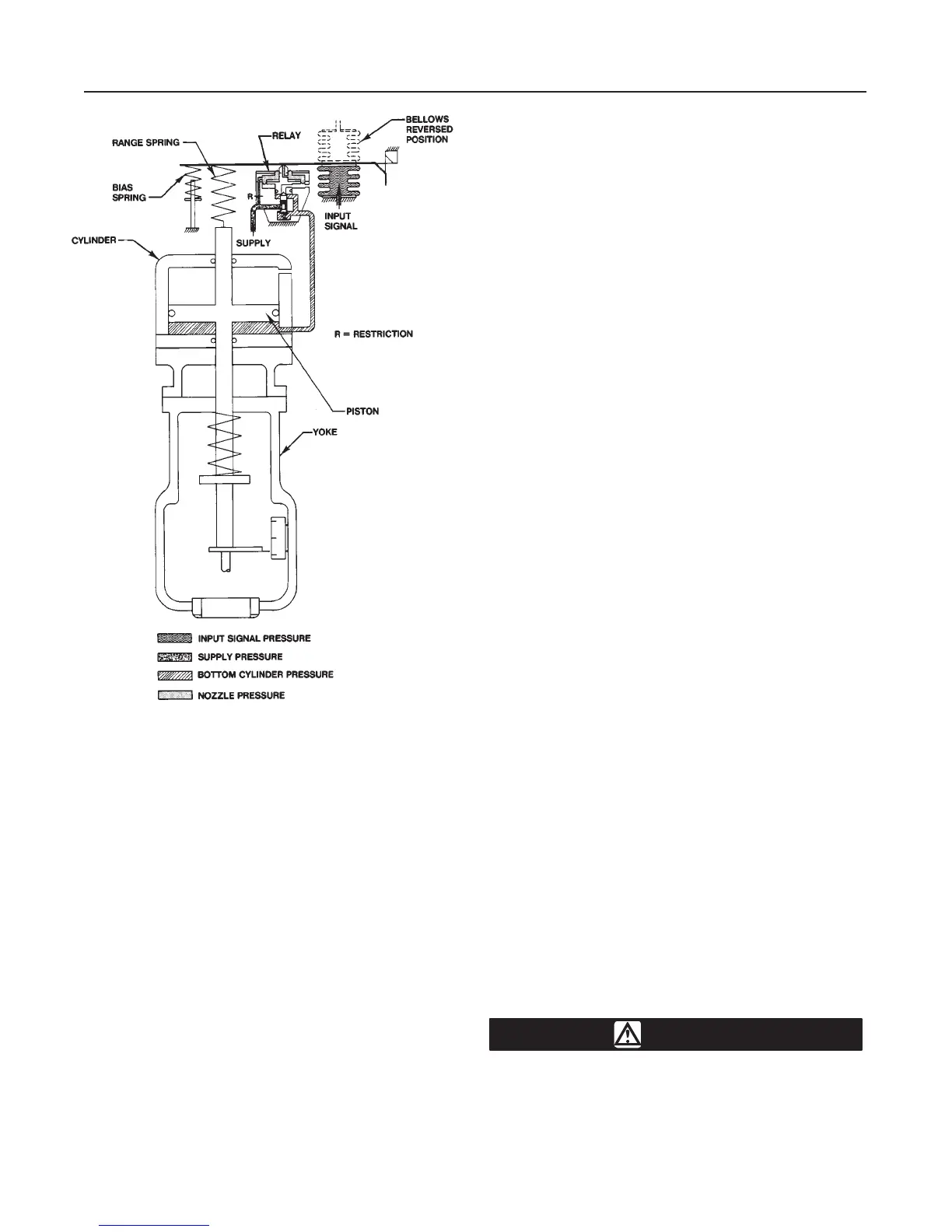
Figure 9. Schematic Diagram of T
ype 3573 Positioner with
T
ype 473 Pneumatic Piston Actuator
CR4007-A
A1082-1/IL
Relay Operation
Refer to figure 10, which shows a sectional view of a
typical relay.
Supply pressure reaches the relay(s) through pas-
sages in the positioner base and is channeled to fixed
restriction R and to point A between the supply valve
B and the balancing O-ring of the relay valve. The
fixed restriction is an integral part of the relay restric-
tion plug and wire assembly G. The orifice in nozzle F
is larger than the fixed restriction. This allows the sup-
ply pressure to bleed to atmosphere faster than it en-
ters the unit through the fixed restriction when the
beam flapper is away from the nozzle.
Assume that a change in the input signal causes the
beam flapper to cover the nozzle of a relay. The sup-
ply pressure flows through fixed restriction R into the
chamber between the two relay diaphragms. Due to
the restricting effect of the flapper over the nozzle,
pressure builds up in the chamber between the dia-
phragms, forcing the diaphragm head assembly E
downward to open supply valve B, allowing output
pressure to increase.
The supply pressure flows past supply valve B to in-
crease the output pressure to the actuator cylinder.
The cylinder pressure (relay output pressure) also acts
on the area D. This provides an air feedback that re-
turns the diaphragm head assembly E and the mov-
able nozzle F to their original positions, thus prevent-
ing any further increase in output pressure. The
feedback arrangement and the movable nozzle ensure
accurate and stable positioning of the actuator piston
without introducing cycling or over-correction. After
any change in the output pressure, supply valve B and
exhaust valve C always return to the closed position to
put the nozzle back in its original, or equilibrium, posi-
tion. The spring behind supply valve B aids in closing
the valve as the diaphragm head assembly is forced
upward.
When the beam flapper moves away from the nozzle
F, the supply pressure bleeds out at a greater rate
than it enters through the fixed restriction R. The pres-
sure then decreases in the chamber between dia-
phragms. The force of the cylinder pressure acting on
area D pushes diaphragm head assembly E upward,
opening exhaust valve C. Cylinder pressure bleeds
through the exhaust port to atmosphere. As the cylin-
der pressure decreases and the force on area D de-
creases, the force of the nozzle pressure in the cham-
ber between the diaphragms returns the assembly to
its original position. The unit is again in equilibrium, but
at a lower nozzle pressure and a lower output pres-
sure.
Each relay has a 4:1 ratio between the nozzle pres-
sure and the output pressure. For example, a 10 psig
(0.7 bar) nozzle pressure change, produces a 40 psig
(2.7 bar) output pressure change; a 20 psig (1.4 bar)
nozzle pressure change produces an 80 psig (5.5 bar)
output pressure change. With a constant input signal
pressure, the internal parts of the relay are at equilibri-
um with the supply and exhaust valves closed.
Maintenance
WARNING
Avoid personal injury from sudden re-
lease of process pressure. Before per-
forming any maintenance operations: