3570 Series
17
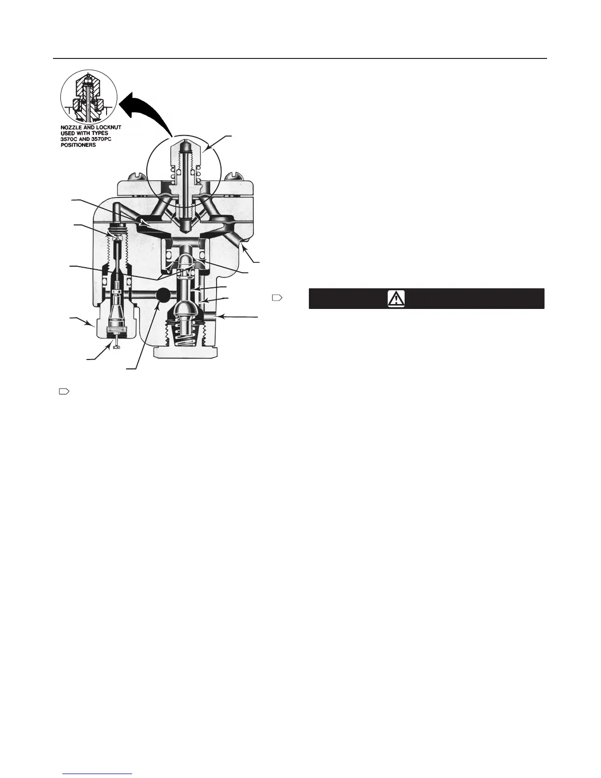
Figure
10. Sectional V
iew of a T
ypical Relay
W0700-1/IL
CLEAN-OUT
PLUNGER
SUPPLY
OUTPUT
B
A
C
EXHAUST
F
E
R
D
G
A–SUPPLY PRESSURE AREA
B–RELAY OUTPUT PRESSURE VALVE
C–EXHAUST VALVE
D–RELAY OUTPUT PRESSURE AREA
E–DIAPHRAGM HEAD ASSEMBLY
F–NOZZLE
G–RELAY RESTRICTION PLUG ASSEMBLY
R–FIXED RESTRICTION
NOTES:
OUTPUT PORT IS SHOWN
90 DEGREES TO THE FRONT OF
ACTUAL LOCATION
1
1
40A8972-B/DOC
D Disconnect any operating lines pro-
viding air pressure, electric power, or a
control signal to the actuator. Be sure
the actuator cannot suddenly open or
close the valve.
D Use bypass valves or completely
shut off the process to isolate the valve
from process pressure. Relieve process
pressure on both sides of the valve.
Drain the process media from both
sides of the valve.
D Vent the power actuator loading
pressure and relieve any actuator spring
precompression.
D Use lock-out procedures to be sure
that the above measures stay in effect
while you work on the equipment.
Troubleshooting
If the positioner causes sluggish or erratic operation or
the malfunctioning of the actuator, first, be certain that
the range springs, bias springs, and spring retainer are
correct for the application. Refer to table 4 or consult
your Fisher sales office or sales representative.
If the springs and spring retainer are correct, and care-
ful adjustment of the unit does not produce smooth
and satisfactory operation, check the following points.
Key numbers used in this procedure are shown in fig-
ure 11 except where indicated. Figure 2 shows part
locations.
1. Clean out the primary orifice on each relay by de-
pressing the clean-out plunger. The plunger is located
in the orifice assembly (key 29S). This operation runs
a fine wire through the orifice to clear the hole.
2. Check the nozzle (key 29Q) of each relay for plug-
ging. To clean, swing the flapper (key 12) away from
the nozzle by loosening the screw that holds the flap-
per in place.
CAUTION
The relays used in Type 3570C and
3570PC positioners use a locknut (key
29P, figure 12) on the nozzle (key 29Q,
figure 12). If the nozzle is rotated when
the locknut is tight, damage to the relay
diaphragm will result. Always use a
wrench on the nozzle to prevent it from
turning while loosening or tightening
the locknut.
Unscrew the nozzle and run a fine wire through it. Do
not enlarge the hole. Also check the surface of the
flapper for any accumulation of dirt or foreign materi-
als.
3. Check the bellows assembly for damage, misalign-
ment, or leakage. Also check all gasketed joints for
leakage. Use soap solution for leak detection.
4. Check the beam for damage, binding or rubbing
against stationary parts. Check the flexure strip
screws (key 17) for tightness.
5. If the positioner operation has improved, refer to
the adjustment procedures.
6. If the positioner operation does not improve, go to
step 7.
7. Unscrew the three machine screws (key 31) from
each relay and remove the relays.
8. Check the two relay diaphragms (keys 29F and
29K) for holes or cuts. Note that the larger of the two
diaphragms has five holes in it: four holes are for the
flange screws and one permits the flow of air from the
primary orifice to the chamber between diaphragms.
9. Check the relay valve plug (key 29B) for nicks,
cuts, or dirt. Also check both inlet and exhaust ports.
 Loading...