3570 Series
11
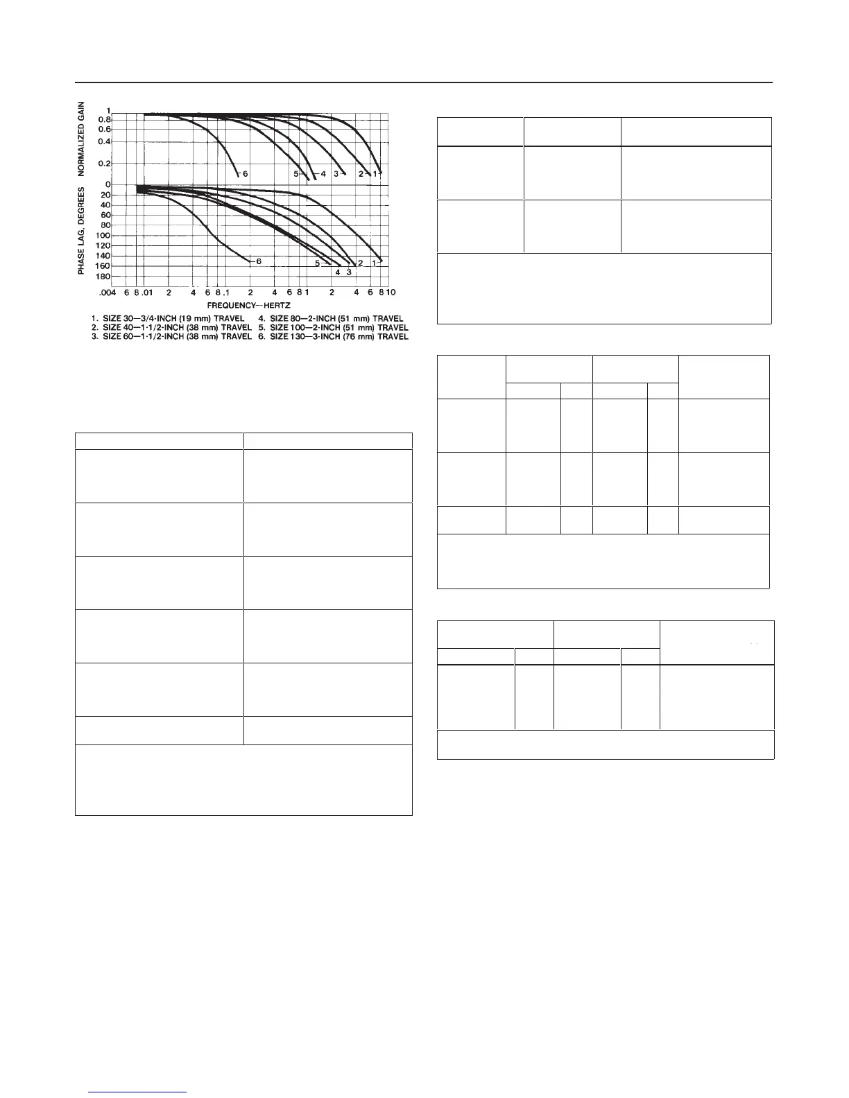
Figure 5. Typical Frequency Response for a T
ype 3570 or
3570C Positioner Mounted on a T
ype 470 or 480 Actuator
2K5255-R
A1285-2/IL
Table 5. Range
(1)(2)
Code Number Part Number
(3)
1
2
3
4
1H8914 000A2
1H8915 000A2
1H8916 000A2
1H8917 000A2
5
6
7
8
1H8918 000A2
1H8919 000A2
1H8920 000A2
1H8921 000A2
9
10
11
12
1H8922 000A2
1H8955 000A2
1H8956 27012
1H8957 000A2
13
14
15
16
1J5185 000A2
1J5715 000A2
1K5363 000A2
1K6684 000A2
17
18
19
20
1R6135 27012
1R2822 000A2
1R8535 27012
1R8998 27012
21
22
1U5827 27012
17A3811 X022
1. The range spring code number is the first number given in each signal range code
listed in table 4. For example, for a signal range of 0 to 15 psig (0 to 1.0 bar), an
actuator travel of 9/16-inch (14.3 mm), and direct action, the signal range code from
table 4 is 6G3. The appropriate range spring is indicated by “6”.
2. Range springs do not have a color code. All range springs are silver.
3. The first six numbers of a range spring part number is also the tag number. For
example, a range spring with part number 1H8914 000A2 has a tag number of
1H8914. Tags are attached to the parts at the time the parts are manufactured.
If the relay output pressures are not at the values
mentioned, adjust the nozzles. Counterclockwise rota-
tion of either nozzle will move the nozzle closer to the
beam and will increase relay output pressure.
For all 3570 Series positioners, examine the end of the
beam near the bias spring (see figure 3). The beam
should be approximately centered between the twoE-
ring travel stops. Observing the caution above for
Type 3570C and 3570PC positioners, rotate the
nozzle(s) to center the beam between the E-rings. For
Table 6. Bias Spring
(1)(2)
Code
Letter
Color
Code
Part
Number
A
B
C
D
Silver
Light blue
Red
Light green
1H8618 27012
(3)
1H8932 27012
(3)
1H8933 27012
(3)
1H8968 27012
(3)
E
F
G
H
Dark green
Pink
Black
Brown
1J2932 X00A2
(4)
1J2933 000A2
(4)
1N7177 000A2
(4)
1R6134 27012
(3)
1. The bias spring code letter is the letter given in each signal range code listed in
table 4. For example, for a signal range of 0 to 15 psig (0 to 1.0 bar), an actuator
travel of 9/16-inch (14.3 mm), and direct action, the signal range code from table 3
is 6G3. The appropriate bias spring is indicated by “G”.
2. It is necessary to add the bias spring seat (key 8) to a unit when changing from
an extensin type spring (key 9) to a compression type spring (key 48).
3.Compression type bias spring (key 48).
4. Extension type bias spring (key 9).
Table
7. Spring Retainer
CODE
OVERALL
LENGTH
(2)
EFFECTIVE
LENGTH
(2) PART
NUMBER
Inches mm Inches mm
NUMBER
1
2
3
4
2-15/64
2-5/64
1-63/64
1-7/8
57
53
50
48
1-47/64
1-37/64
1-31/64
1-3/8
44
40
38
35
1H890724102
1H890824102
1H890924102
1H891124102
5
7
8
10
1-11/16
31/32
7/8
1-3/8
43
25
22
35
1-3/16
15/32
3/8
55/64
30
12
10
22
1H891024102
1H891224102
1H855224102
1H891324102
12
13
1-1/2
1-1/8
38
29
1
21/32
25
16
1J357224102
1J979624102
1. Code numbers 6, 9, and 11 are not used.
2. Refer to figure 3.
3. The spring retainer code number is the second number given in each signal
range code listed in table 4. For example, for a signal range of 0 to 15 psig (0 to 1.0
bar), an actuator travel of 9/16-inch (14.3 mm), and direct action, the signal range
code from table 4 is 6G3. The appropriate spring retainer is indicated by “3”.
Table
8. Spring Retainer Spacer
OVERALL
LENGTH
(1)
EFFECTIVE
LENGTH
(1)
PART NUMBER
(2)
Inches mm Inches mm
1-5/8
2-1/16
2-1/4
3-11/16
3-13/16
41
52
57
94
97
1-1/8
1-9/16
1-3/4
3-3/16
3-5/16
29
40
44
81
84
1L2069X0012
1J223346172
1J803846172
1P3957X0012
1J803946172
1. Refer to figure 3.
2. The spacer number is the first 6 characters of the part number and is stamped on
the part.
positioners with two relays, the relay output pressures
must be approximately equal [within 5 psig (0.3 bar)]
and approximately 75 percent of supply pressure after
the beam is centered.
7. Apply an input signal equal to the low value of the
input signal range [3 psig (0.2 bar) in this example].
Adjust the bias spring (see figure 3) up or down until
the valve travel is at the starting point.
8. Loosen the spring lock (see figure 3) and slowly
increase the input signal toward the high end of the
input signal range [15 psig (1.0 bar) in this example]. If
the valve travel is less than its expected range, in-
crease the travel by adjusting the range spring coun-
terclockwise. If the valve travel reaches the end of its
 Loading...