3570 Series
10
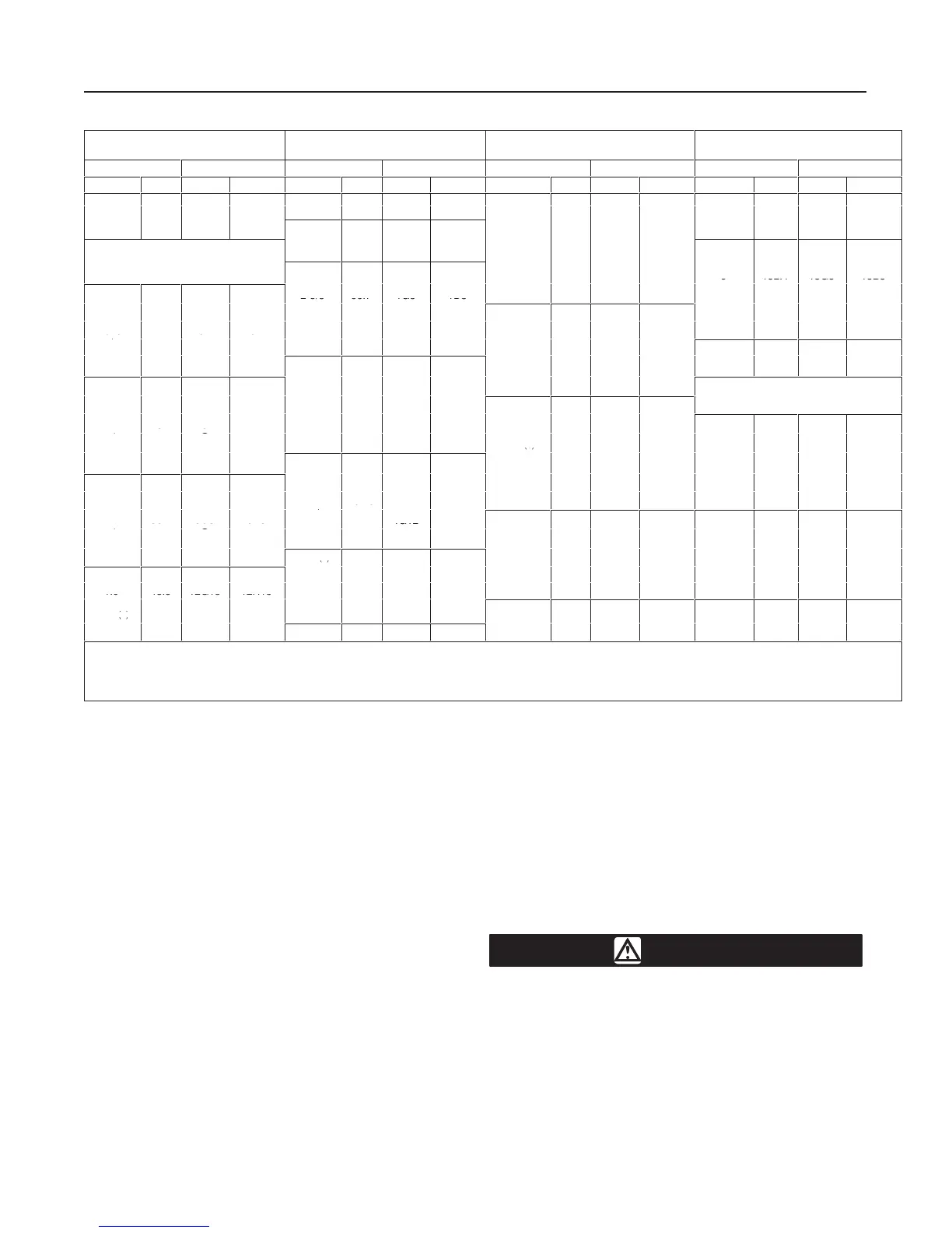
Table
4. Type 3570 Signal Range Codes
(9)
(Continued)
SIGNAL RANGE
6 to 18 psig (0.4 to 1.2 bar)
SIGNAL RANGE
6 to 30 psig (0.4 to 2.0 bar)
SIGNAL RANGE
9 to 15 psig (0.6 to 1.0 bar)
SIGNAL RANGE
9 to 15 psig (0.6 to 1.0 bar)
Travel Code Travel Code Travel Code Travel Code
Inches mm Direct Reverse Inches mm Direct Reverse Inches mm Direct Reverse Inches mm Direct Reverse
6-1/2
(4)
165.1
13G3
13A3
2-1/4 57.1 12G1 12D1
4-1/8
104.8
14G8
14B8
8-1/8 206.4 19G5 19C5
2.3 58.4 12G3 12C3
11/32
7/16
8.7
11.1
5A13
5G5
5D13
5B5
4-5/8 117.5 13G3 13B8
SIGNAL RANGE
.
2-3/8
.
60.3
12A10
12D10
1/2
.
12.7
12G13
12B13
6 to 30 psig (0.4 to 2.0 bar)
-
5
11/16
5.
17.5
8G8
8C8
5
(2)
6
127
152.4
13G12
13G3
13B12
13B3
-
2-5/8
.5
66.7
1G3
1D3
6-1/8
-
155.6
13G4
13B4
1/4
(5)
6.4
.
17H4
1
A4
17H4
1
H4
2-3/4
69.9
1G4
1D4
-
7
5.
177.8
13G3
13B3
7/16
.
11.1
10A2
10H2
3
3-1/8
76.2
79.4
1G1
4G1
1D1
4C1
3/4
19
8G10
8B10
.
1/2
12.7
10A2
10D2
-
.
1-1/8
.
28.6
9G8
9B8
8 203.2 18G8 18B8
5/8 15.9 3G2 3H2
1-1/2
-
.
38.1
9F8
9B8
8-1/8
.
206.4
18G8
18B8
3-1/4
3-5/16
82.6
84.1
4G1
4G3
4C1
4D3
1-5/8 41.3 9F8 9B8
SIGNAL RANGE
3/4
19
11G4
11H4
-
3-3/8
.
85.7
4G1
4H1
18 to 30 psig (1.2 to 2.0 bar)
1
.
25.4
2G4
2D4
3-1/2
3-9/16
88.9
90.5
1G12
4G1
1D12
4D1
2
50.8
15G8
15B8
1-1/32
-
26.2
2G4
2H4
-
.
2-1/8
2-1/8
(8)
54
54
15G1
15F5
15B1
15B5
3/4
1-1
19
2
.
5G10
5D10
D
-
.
2-5/16
-
58.7
15G1
15C1
-
1-1/2
.
38.1
8F5
8C5
3-21/32
-
4
92.9
.
4G14G
4D1
4D1
2-1/2
2-7/8
63.5
73
15F1
14G8
15A1
14B8
2
3
50.8
76.2
4F8
9G8
4D8
9H8
1-1/4
-
31.8
2G5
2D5
-
4
.
101.6
1
4D4
.
-
1-1/2
38.1
5G5
5D5
4-1/8
(5)
104.8
4G12
4D12
1-9/16
-
39.7
5G5
5D5
21A5
3
3-1/8
76.2
79.4
14G8
14G8
14B8
14B8
3-1/8
3-1/4
79.4
82.6
9F8
9F8
9C8
9C8
-
.
5-1/4
(5)
133.4 21A13 21D13
3-1/4
.
82.6
14G8
14B8
4
(5)
.
101.6
14E8
14D8
1-13/16 46 5G5 5D5
5-5/8
(5)
.
142.9
16G1
16D1
3-7/16
-
87.3
14G8
14B8
4-1/8
(4)
104.8
16F8
16D8
-
1.9
48.3
12G13
12H13
6
(4)
152.4
16G3
16C3
-
.
2
50.8
12C8
12C8
6-1/2
165.1
16G1
16C1
-
-
(2)
2-1/8
(2)
.
54
12G7
12D7
7
(3)
177.8 21G12 21D12
-
-
.
-
-
4
.
2-1/8
(8)
54
12G13
12D13
8
(3)
203.2 21E12 21D12
-
4
.
101.6
14G8
14A8
-
8-1/8
(4)
206.4
18F1
18D1
1. Use spring retainer spacer 1J8038 46172; for additional information, see table 7.
2. Use spring retainer spacer 1J2233 46172; for additional information, see table 7.
3. Use spring retainer spacer 1J8039 46172; for additional information, see table 7.
4. Use with high pressure bellows and spring retainer spacer 1J8039 46172; for additional
information, see table 7.
5. Use with high pressure bellows.
6. Use with high pressure bellows and spring retainer spacer 1J2233 46172; for additional
information, see table 7.
7. Use spring retainer spacer 1P3957 X012; for additional information, see table 7.
8. For use with Type 480-12 or 480-15 size 20 actuators.
9. For Type 3570P signal range codes, contact your Fisher sales office or sales
representative.
3. Provide a means for varying the input signal pres-
sure from zero to 1 or 2 psig (0.07 or 0.14 bar) above
the higher value of the input signal range (see table 1).
Provide an accurate means of measuring the input
signal pressure. Check the accuracy of the positioner
instrument pressure gauge (see figure 2). The gauge
accuracy is±0.6 psig (±0.04 bar) on a 0 to 30 psig (0 to
2 bar) gauge, and ±1.2 psig (±0.08 bar) on a 0 to
60 psig (0 to 2 bar) gauge. This accuracy is measured
at the mid-point of the full range of the scale.
4. Set the input signal pressure at the mid-point of its
range [9 psig (0.6 bar) in this example]. Observe the
valve travel indicator scale attached to the yoke. The
indicator disk should be somewhere between the open
and closed positions.
5. Loosen the locknut directly below the bias spring
seat (see figure 3) and adjust the bias spring up or
down until the valve travel indicator disk shows that
the valve plug is somewhere between the open and
closed positions. Upward movement of the bias spring
adjustment causes downward travel of the valve stem.
6. For positioners with two relays (Type 3570, 3570C,
3570P, 3570PC, and 3571 positioners), observe the
relay output pressures. If the cylinder gauges are
present as shown in figure 2, read the cylinder top and
cylinder bottom gauges or use clip-on test pressure
gauges. The two relay output pressures should be
approximately equal [within 5 psig (0.3 bar)] and
should be approximately 75 percent of the supply
pressure. For example, if the supply pressure is 100
psig (7 bar), the two relay output pressures should be
within 5 psig (0.3 bar) of each other, and should be
approximately 75 psig (5.2 bar).
CAUTION
The relays in the Type 3570C and 3570PC
positioners use a locknut (key 29P, figure
11) on the nozzle (key 29Q). If the nozzle
is rotated when the locknut is tight, dam-
age to the relay diaphragm might result.
Always use a wrench on the nozzle to
prevent it from turning while loosening or
tightening the locknut.
 Loading...