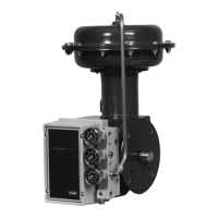
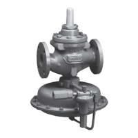
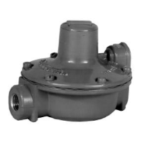
4195KA, KB, and KC Series
1–4
Table 1–1. Specifications
Available Configurations
See table 1–2
Input Signal (Process Sensor Range)
(1)
Lower and Upper Range Limits: See tables 1–3
and 1–4
Maximum Allowable Operating Limits: See
tables 1–3 and 1–4
Output Signal
(1)
Proportional-Only, Proportional-Plus-Reset, or
Proportional-Plus-Reset-Plus-Rate Range: 3 to
15 psig or 6 to 30 psig (0.2 to 1.0 bar or 0.4 to 2.0
bar)
Action: Field-reversible between direct(increasing
sensed process pressure increases output pres-
sure) or reverse(increasing sensed process pres-
sure decreases output pressure).
Process Scale
Standard scale is matched to the range of the sens-
ing element, with the exception of receiver control-
lers. Optional
(2)
scales are available.
Process Connections
Standard: 1/4-inch NPT, female, stainless steel (all
input ranges)
Optional: 1/2-inch NPT. See table 1–5.
Supply and Output Connections
1/4-inch NPT, female
Supply Pressure Requirements
See table 1–6.
Remote Set Point Pressure Ranges
3 to 15 psig or 6 to 30 psig (0.2 to 1.0 bar or 0.4 to
2.0 bar)
Controller Adjustments
Proportional Band
(1)
: 5 to 500% of process input
span
Reset
(1)
: Adjustable from 0.01 to more than 74 min-
utes per repeat (from 100 to less than 0.0135 re-
peats per minute)
Rate
(1)
: Adjustable from 0 to 20 minutes
Set Point: Adjustable from 0 to 100% of the scale
span
Controller Performance
Repeatability
(1)
: 0.4% of output span
Dead Band
(1)
: Less than 0.4% of process scale
span
Typical Frequency Response: 1.5 hertz and 90
degree phase shift with 10 feet (3.05 m) of 1/4-inch
(6.4 mm) tubing and 100 cubic inch (1639 cm
3
) vol-
ume
Steady-State Air Consumption
(1,3,4)
3 to 15 Psig (0.2 to 1.0 Bar) Output:
3.5 scfh (0.1
m
3
/hr)
6 to 30 Psig (0.4 to 2.0 Bar) Output:
5.0 scfh (0.14
m
3
/hr)
Delivery Capacity
(3)
3 to 15 Psig (0.2 to 1.0 Bar) Output:
240 scfh (5.9
m
3
/hr)
6 to 30 Psig (0.4 to 2.0 Bar) Output:
350 scfh (10.4
m
3
/hr)
Exhaust Capacity
(3)
3 to 15 Psig (0.2 to 1.0 Bar) Output:
186 scfh (4.6
m
3
/hr)
6 to 30 Psig (0.4 to 2.0 Bar) Output:
295 scfh (7.0
m
3
/hr)
Operative Ambient Temperature Limits
(1)
–40 to 160_F (–40 to 71_C)
Mounting
Controller can be mounted on actuator, panel, wall,
or pipestand.
Approximate Weight
10 pounds (4.5 kg)
1. These terms are defined in ISA Standard S51.1-1979.
2. Consult your Fisher sales office or sales representative for additional information.
3. Scfh—Standard cubic feet per hour (60_F and 14.7 psia). Normal m
3
/hr—Normal cubic meters per hour (0_C and 1.01325 bar, absolute).
4. Without auto/manual station. With auto/manual station, air consumption is 10.0 Scfh (0.28 normal m
3
/hr for either output range.

 Loading...


