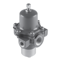
67C Series
2
1/4 NPT
250 psig (17,2 bar)
400 psig (27,6 bar)
See Table 1
50 psi (3,4 bar) over outlet pressure setting
C
g
: 11.7; C
v
: 0.36; C
1
: 32.2
C
g
: 1.45; C
v
: 0.045; C
1
: 32.8
X
T
: 0.66; F
L
: 0.89; F
D
: 0.50
Less than 0.2 psig (14 mbar)
change in outlet pressure for every 25 psig
(1,7 bar) change in inlet pressure
0.1 psig (7 mbar)
(2)
Testing repeatedly shows
no discernible leakage
Low capacity for minor seat leakage only; other
overpressure protection must be provided if inlet
pressure can exceed the maximum pressure rating
of downstream equipment or exceeds maximum
outlet pressure rating of the regulator.
1 pound (0,5 kg)
2.5 pounds (1 kg)
4 pounds (2 kg)
Standard Bolting: -20° to 180°F (-29° to 82°C)
Stainless Steel Bolting: -40° to 180°F (-40° to 82°C)
Polyethylene Filter
(5)
(Standard):
0° to 180°F (-18° to 82°C)
Polyvinylidene (PVDF), SST, or Glass Filter (Optional):
0° to 300°F (-18° to 149°C)
-60° to 180°F (-51° to 82°C)
-20° to 180°F (-29° to 82°C)
6 psi (0,41 bar) differential
12 times pipe area
Polyethylene Filter
(5)
(Standard): 5 microns
Glass Fiber Filter (Optional): 5 microns
PVDF or Stainless Steel Filter (Optional):
40 microns
Aligned with inlet standard, other positions optional
Internal
• Handwheel adjusting screw
• Inlet screen
• NACE MR0175 or NACE MR0103 construction
(4)
• Panel mount (includes spring case with 1/4 NPT
vent, handwheel, and panel mounting nut)
• Closing cap (available on spring case with
1/4 NPT vent)
• Fluorocarbon (FKM) elastomers for high
temperatures and/or corrosive chemicals
• Silicone (VMQ) elastomers for cold temperatures
• Fixed Bleed Restriction
• Triple scale outlet pressure gauge (brass or
stainless steel)
• Stainless steel stem on the valve plug
• Tire valve or pipe plug in second outlet
• Smart Bleed
TM
internal check valve
• Large dripwell with manual or automatic drain
• Stainless steel drain valve
1. The pressure/temperature limits in this Instruction Manual and any applicable standard or code limitation should not be exceeded.
2. Repeatability is the measure of the regulator’s ability to return to setpoint consistently when traveling from steady state to transient to steady state.
3. Silicone (VMQ) is not compatible with hydrocarbon gas.
4. Product complies with the material requirements of NACE MR0175. Environmental limits may apply.
5. Do not use in high aromatic hydrocarbon service.
 Loading...