Instruction Manual
D104016X012
8590 Valve
June 2017
7
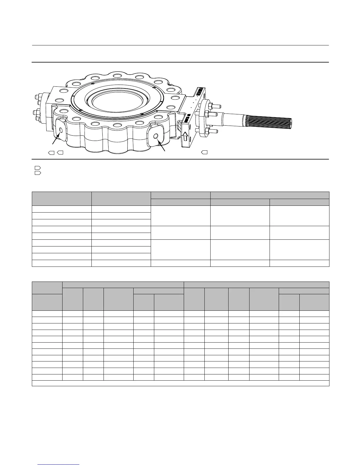
Figure 3. Lifting Thread Locations (NPS 10 shown)
LIFTING THREAD
LIFTING THREAD
Notes:
Holes on opposite side are identical.
NPS 10-24 only.
2
1
1
1
2
Table 5. Valve Body Lifting Thread Information
NPS
NUMBER OF THREADED
HOLES
THREAD SIZE THREAD DEPTH
Inches mm Inches
6 2
3/4 - 10 41.9 1.65
8 2
10 4
12 4
1 - 8 55.9 2.20
14 4
16 4
1-1/4 - 7 68.8 2.71
18 4
20 4
24 4 1-1/2 - 6 82.8 3.26
Table 6. Recommended Line Bolting Lengths
VALVE SIZE
LUGGED BODY WITH THROUGH HOLES LUGGED BODY WITH THREADED HOLES
Size Dia &
Thread,
Inch
No. of
Stud
Bolts
A Dimension,
Inch
Next to Shaft Bore
No. of
Stud
Bolts
C
Dimension,
Inch
No. of
Stud
Bolts
B
Dimension
(1)
,
Inch
Next to Shaft Bore
NPS
No. of
Stud
Bolts
B
Dimension
(1)
,
Inch
No. of
Stud
Bolts
B
Dimension
(1)
,
Inch
3 3/4 - 10 8 7.5 - - - - - - 8 7.5 - - - - - - - - - - - -
4 7/8 - 9 8 9 - - - - - - 8 9 - - - - - - - - - - - -
6 1 - 8 12 10.5 - - - - - - 12 10.5 - - - - - - - - - - - -
8 1-1/8 - 8 12 12.5 - - - - - - 12 12.5 - - - - - - - - - - - -
10 1-1/4 - 8 12 13.5 8 6 - - - - - - 24 7.5 8 6
12 1-1/4 - 8 16 14.5 8 6 - - - - - - 32 7.5 8 6
14 1-3/8 - 8 16 15.75 8 6.5 - - - - - - 32 8 8 6.5
16 1-1/2 - 8 16 17.25 8 7 - - - - - - 32 8.5 8 7
18 1-5/8 - 8 16 19 8 7.5 - - - - - - 32 9 8 7.5
20 1-5/8 - 8 20 20 8 8 - - - - - - 40 9.5 8 8
24 1-7/8 - 8 20 22.25 8 9 - - - - - - 40 11 8 9
1. Full stud thread engagement as shown in figure 4.