Instruction Manual
D104016X012
8590 Valve
June 2017
8
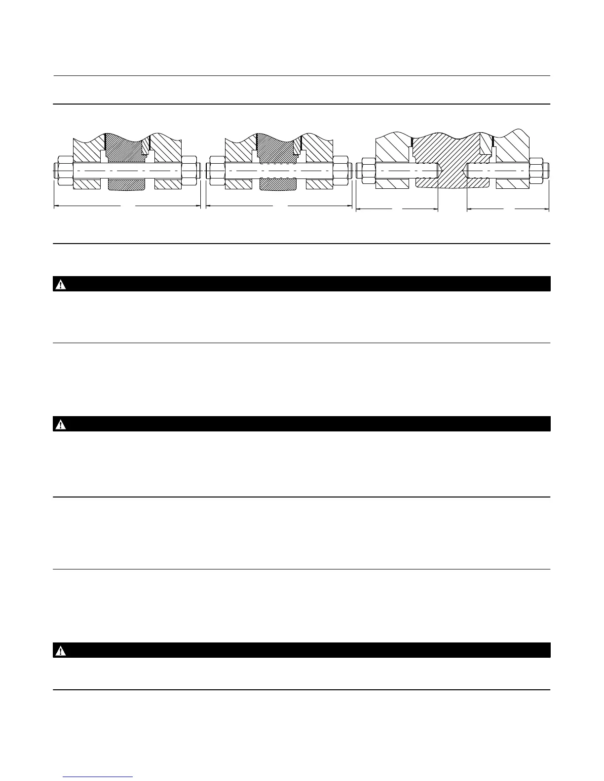
Figure 4. Stud Bolts for Installation (also see table 6)
LUGGED VALVE BODY
WITH THROUGH HOLES
LUGGED VALVE BODY WITH THREADED HOLES
A
C
BB
WARNING
For lugged valve bodies with threaded line bolt holes, personal injury and property damage could result from sudden
release of process pressure if line bolts are not properly installed. To ensure proper line bolt thread engagement, line studs
must be centered in the threaded section of the valve body so that each stud has equal thread engagement in the body. See
figure 4.
8. After centering the valve body, first lubricate and then install the remaining line flange bolting to secure the valve in
the pipeline. Tighten the nuts to the line flange studs in a crisscross pattern to ensure proper alignment of valve,
gaskets, and flanges.
WARNING
An 8590 valve body is not necessarily grounded when installed in a pipeline. If the valve is used in a flammable or hazardous
atmosphere or for oxygen service, an explosion could result due to a discharge of static electricity from the valve
components. To avoid personal injury or property damage, always make sure the valve body is grounded to the pipeline
before putting the control valve assembly into operation in a flammable or hazardous atmosphere.
Note
Standard packings for the 8590 valve are composed of all conductive packing rings (graphite ribbon packing) or partially
conductive packing rings (such as a carbon‐filled PTFE female adaptor with PTFE V‐ring packing) to electrically bond the shaft to
the valve body for hazardous area service. For oxygen service applications, provide alternate shaft‐to‐valve body bonding
according to the following step.
9. For oxygen service applications, attach the bonding strap assembly (key 34, figure 5) to the shaft with the clamp
(key 33, figure 5), and connect the other end of the bonding strap assembly to the valve body with the cap screw
(key 31).
WARNING
Personal injury could result from packing leakage. Valve packing was tightened prior to shipment; however, the packing
might require some readjustment to meet specific service conditions.