Designs D & DA
2
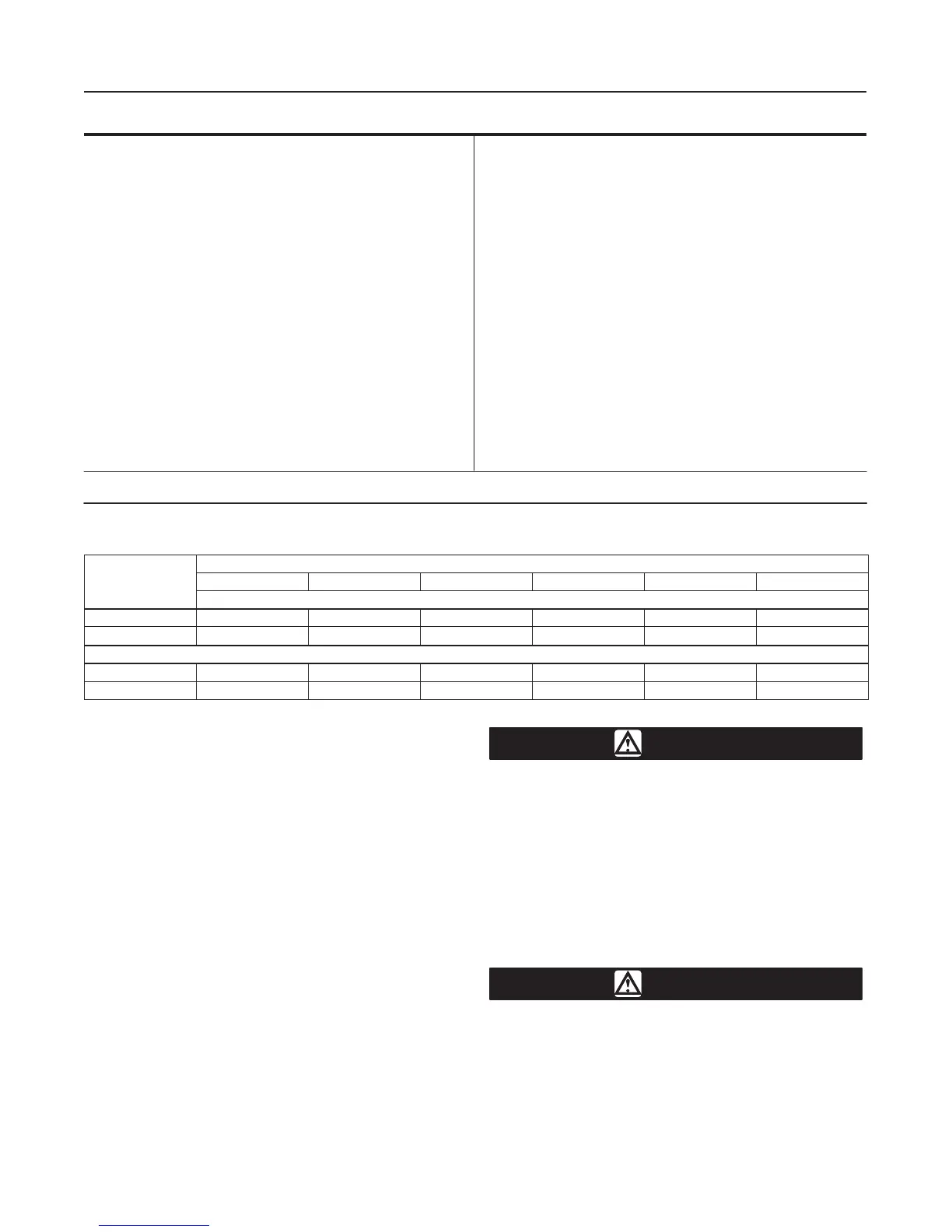
Table 1. Specifications
Maximum Inlet Pressures and Temperatures
(1)
If the valve nameplate shows an ANSI pressure-
temperature class, maximum inlet pressure and
temperature is consistent with applicable ANSI
class per ASME B16.34.
If the nameplate does not show an ANSI class, it
will show a maximum cold working pressure at
100_F (38_C) (for example, 3600, 6000, 9000, or
10,000 psi)
Maximum Allowable Pressure Drops
(2)
Flow up: Capable of full rated pressure drops
Flow down: See table 2 for pressure drop limits for
ceramic trim
Shutoff Classification Per ANSI/FCI 70-2
Standard: Class IV
Optional: Class V
Maximum Service Temperature
450_F (232_C)
Flow Characteristic
Equal Percentage
Flow Direction
Design D Valve: Flow up through the seat ring and
out past the valve plug
Design DA Valve: Flow in either direction
Approximate Weight
Design D: 75 pounds (34 kg)
Design DA: 100 pounds (46 kg)
1. Do not exceed the pressure or temperature limits in this manual and any applicable standard limitations.
2. The pressure-temperature limits in this manual and in any applicable standard limitations should not be exceeded.
Table 2. Flow Down Pressure Drop Limits - Ceramic Trim Only
SEAT RING DIAMETER, INCHES (mm)
VALVE SIZE
1/4 (6.4) 3/8 (9.5) 1/2 (12.7) 3/4 (19.1) 1 (25.4) 1-1/4 (31.8)
Pressure Drop, psi
1 6000 6000 6000 2800 - - - - - -
2 10,000 10,000 10,000 6700 3800 2400
Pressure Drop, bar
1 414 414 414 193 - - - - - -
2 689 689 689 462 262 165
Description
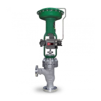
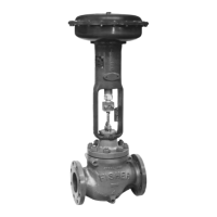
The Design D globe-style (figure 1) and Design DA
angle-style (figure 4) valves are single-port, metal-
seated valves for high-pressure applications.
Specifications
Specifications for these valves are in table 1. Some of
the specifications for a given valve appear on a name-
plate, which is attached to the valve actuator or wired
to the valve assembly if the valve was purchased with-
out an actuator.
Ceramic Trim
Some types of ceramic trim, including the VTC (very
tough ceramic) variety, can create a spark under cer-
tain circumstances. When the edge of a ceramic part
is struck against a second ceramic part with enough
force, a spark can be created.
WARNING
Avoid personal injury and property dam-
age from ignition of process fluid
caused by sparks from ceramic trim.
Do not use ceramic trim where the pro-
cess fluid is unstable or if it is an explo-
sive mixture (such as ether and air).
Installation
WARNING
To avoid personal injury or property
damage resulting from the sudden re-
lease of process pressure or bursting of
parts, do not install the valve assembly
where service conditions could exceed
the limits given in this manual or on the

 Loading...