Design CAV4
3
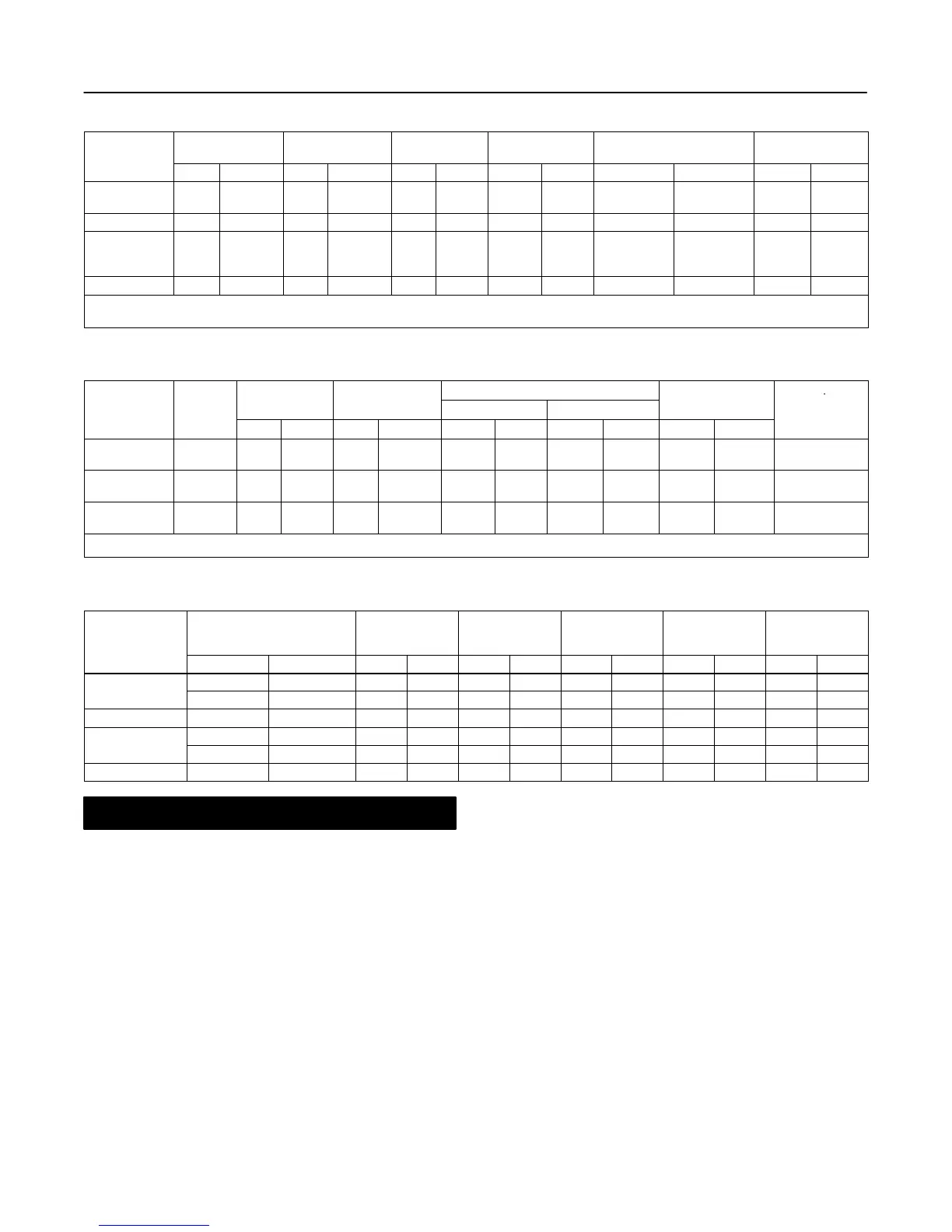
Table 2. Additional Valve Specifications
VALVE SIZE,
VALVE STEM
DIAMETER
YOKE BOSS
DIAMETER
TRAVEL
PORT
DIAMETER
PORT
CIRCUMFERENCE
UNBALANCE
AREA
(1)
INCH
mm Inch mm Inch mm Inch mm Inch mm Inch mm
2
Inch
2
2
19.0
38.1
3/4
1-1/2
(2)
91
127
3-9/16
5
38 1-1/2 38.1 1-1/2 119.6 4.71 4.3 0.17
3 19.0 3/4 91 3-9/16 51 2 55.6 2-3/16 174.5 6.87 6.6 0.26
4
19.0
25.4
69.8
3/4
1
2-3/4
(3)
91
127
178
3-9/16
5
7
64 2-1/2 69.9 2-3/4 219.4 8.64 8.1 0.32
6 31.7 1-1/4 127 5 & 5H 102 4 111.1 4-3/8 349.2 13.75 12.9 0.51
1. For seal ring and piston ring constructions. For stem-balanced construction, use port area of 11.4 cm
2
(1.77 inch
2
) for 2 inch valve and 38.3 cm
2
(5.94 inch
2
) for 4 inch valve.
2. Stem-balanced construction has 31.8 mm (1-1/4 inch) valve stem connection.
3. Stem-balanced construction has 50.8 mm (2 inch) valve stem connection.
Table 3. Additional Valve Specifications for TSO (Tight Shutoff) Trim
MAXIMUM YOKE BOSS
PORT DIAMETER
PORT
C
V
VALVE SIZE,
TRIM
TRAVEL
SIZE
(1)
Nominal Actual TSO
CIRCUMFERENCE
REDUCTION
mm Inch mm Inch mm Inch mm Inch mm Inch
TRAVEL
(2)
2
Class
2500
38 1-1/2
91
127
3-9/16
5
38.1 1-1/2 38.1 1-1/2 119.6 4.71 0%
3
Class
2500
50.8 2 91 3-9/16 55.6 2-3/16 55.6 2-3/16 174.8 6.88 0%
4
Class
2500
64 2-1/2
91
127
3-9/16
5
69.9 2-3/4 69.9 2-3/4 219.4 8.64 0%
1. Consult the factory for larger yoke boss sizes.
2. This column lists the percent reduction of published maximum C
V
of the trim listed in the TRIM column.
Table 4. Approximate Weights
VALVE SIZE,
INCH
YOKE BOSS
DIAMETER
TOTAL
BONNET
ONLY
VALVE PLUG
AND STEM
ASSEMBLY
LOWER CAGE
ASSEMBLY
UPPER
CAGE
mm Inch Kg Lb Kg Lb Kg Lb Kg Lb Kg Lb
91 3-9/16 167 369 44 98 3 7 12 27 4 9
2
127 5 182 401 59 130 3 7 12 27 4 9
3 91 3-9/16 301 664 47 103 5 12 14 30 7 16
91 or 127 3-9/16 or 5 532 1172 127 280 12 27 37 82 12 27
4
178 7 554 1222 150 330 12 27 37 82 12 27
6 127 5 or 5H 1512 3334 240 530 44 98 84 186 54 120
CAUTION
When ordered, the valve configuration
and construction materials were se-
lected to meet particular pressure, pres-
sure drop, temperature, and controlled
fluid conditions. Do not apply any other
conditions to the valve without first con-
tacting your Fisher Controls sales office
or sales representative.
Trim parts, seals, and gaskets may be
damaged if post-weld buttweld heat
treatment is applied to valve areas other
than the end connections. If heat treat-
ment will be performed over the entire
valve body, seals and gaskets must be
removed. Valve plug seals may be re-
used; gaskets that are removed must not
be reused. Use new gaskets upon as-
sembly.
If hoisting the valve, be sure the hoist
used is capable of handling the weight
of the valve and actuator. Also, be sure
the sling does not damage the painted
surfaces, is positioned securely to pre-
vent swinging or slipping, and is posi-
tioned so as to cause no damage to tub-
ing or any accessories.
1. The valve must be installed so that the actuator is
positioned vertically above the valve body. This posi-
tion reduces the possibility of uneven wear on the
valve plug. Also, this position facilitates easier mainte-
nance and prevents stem binding due to actuator
weight.