Quick Start Guide
D103214X012
DLC3010 Digital Level Controller
February 2016
21
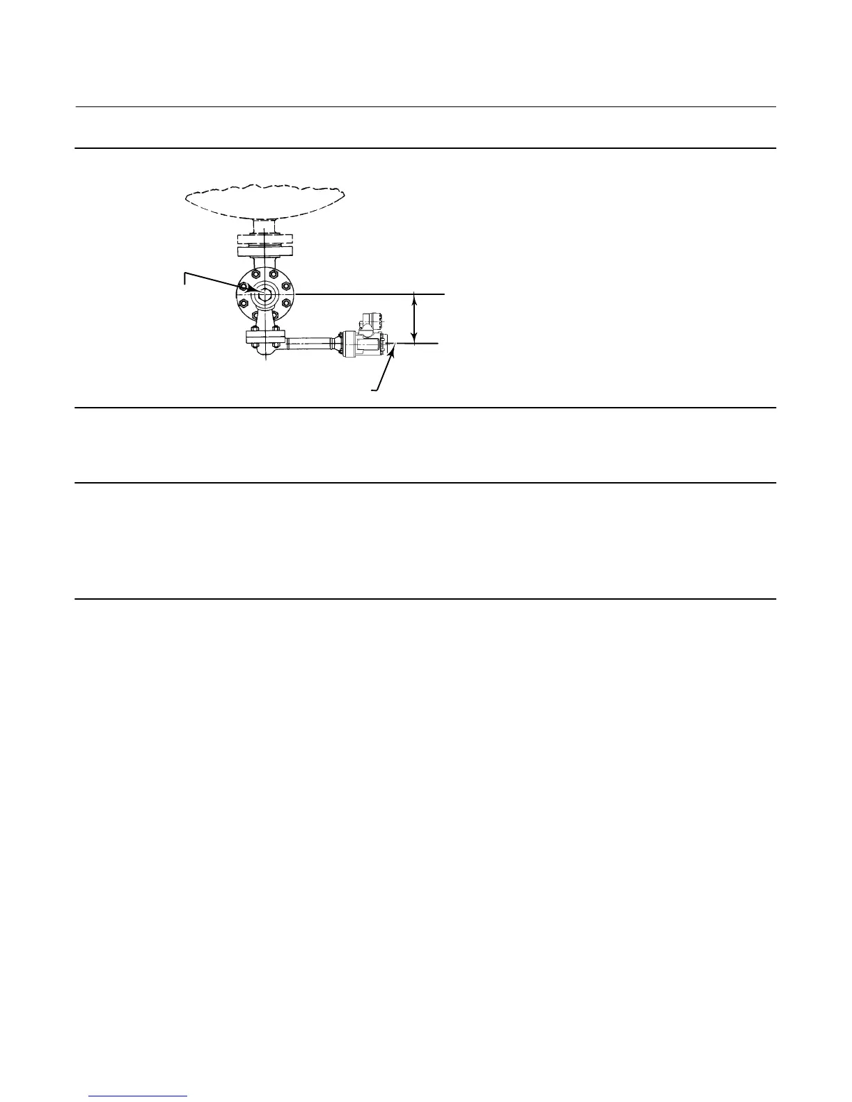
HORIZONTAL C
L
OF TORQUE TUBE
VERTICAL C
L
OF DISPLACER
MOMENT
ARM LENGTH
VESSEL
Figure 12. Method of Determining Moment Arm from External Measurements
E0283
4. Select the measurement application (level, interface, or density).
Note
For interface applications, if the 249 is not installed on a vessel, or if the cage can be isolated, calibrate the instrument with
weights, water, or other standard test fluid, in level mode. After calibrating in level mode, the instrument can be switched to
interface mode. Then, enter the actual process fluid specific gravity(s) and range values.
If the 249 sensor is installed and must be calibrated in the actual process fluid(s) at operating conditions, enter the final
measurement mode and actual process fluid data now.
a. If you choose “Level” or “Interface,” the default process variable units are set to the same units chosen for
displacer length. You are prompted to key in the level offset. Range values will be initialized based on Level Offset
and displacer size. The default upper range value is set to equal the displacer length and the default lower range
value is set to zero when the level offset is 0.
b. If you choose “Density,” the default process variable units are set to “SGU” (Specific Gravity Units). The default
upper range value is set to “1.0” and the default lower range value is set to “0.1”.
5. Select the desired output action: Direct or Reverse.
Choosing “reverse acting” will swap the default values of the upper and lower range values (the process variable values
at 20 mA and 4 mA). In a reverse acting instrument, the loop current will decrease as the fluid level increases.
6. You are given the opportunity to modify the default value for the process variable engineering units.
7. You are then given the opportunity to edit the default values that were entered for the upper range value (PV Value
at 20 mA) and lower range value (PV Value at 4 mA).
 Loading...


