Quick Start Guide
D103214X012
DLC3010 Digital Level Controller
February 2016
20
Guided Setup
Field Communicator Configure > Guided Setup > Instrument Setup (2-1-1)
Note
Place the loop into manual operation before making any changes in setup or calibration.
Instrument Setup is available to aid initial setup. Follow the prompts on the Field Communicator display to enter
information for the displacer, torque tube, and digital measurement units. Most of the information is available from
the sensor nameplate. The moment arm is the effective length of the displacer (driver) rod length, and depends upon
the sensor type. For a 249 sensor, refer to table 5 to determine displacer rod length. For a special sensor, refer to figure
12.
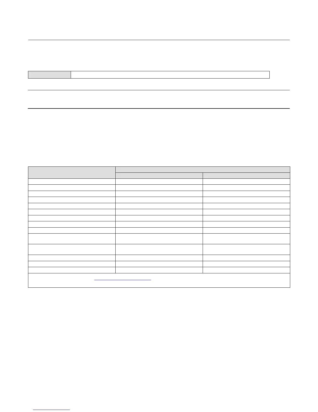
Table 5. Moment Arm (Driver Rod) Length
(1)
SENSOR TYPE
(2)
MOMENT ARM
mm Inch
249 203 8.01
249B 203 8.01
249BF 203 8.01
249BP 203 8.01
249C 169 6.64
249CP 169 6.64
249K 267 10.5
249L 229 9.01
249N 267 10.5
249P
(CL125-CL600)
203 8.01
249P
(CL900-CL2500)
229 9.01
249VS (Special)
(1)
See serial card See serial card
249VS (Std) 343 13.5
249W 203 8.01
1. Moment arm (driver rod) length is the perpendicular distance between the vertical centerline of the displacer and the horizontal centerline of the torque tube. See figure 12. If you cannot
determine the driver rod length, contact your Emerson Process Management sales office
and provide the serial number of the sensor.
2. This table applies to sensors with vertical displacers only. For sensor types not listed, or sensors with horizontal displacers, contact your Emerson Process Management sales office for the
driver rod length. For other manufacturers' sensors, see the installation instructions for that mounting.
1. Enter displacer length, weight, and volume units and values, and driver rod (moment arm) length (in the same units
chosen for displacer length) when prompted.
2. Choose Instrument Mounting (left or right of displacer, refer to figure 5).
3. Choose Torque Tube Material.
 Loading...


