Quick Start Guide
D103214X012
DLC3010 Digital Level Controller
February 2016
13
Electrical Connections
WARNING
Select wiring and/or cable glands that are rated for the environment of use (such as hazardous area, ingress protection and
temperature). Failure to use properly rated wiring and/or cable glands can result in personal injury or property damage
from fire or explosion.
Wiring connections must be in accordance with local, regional, and national codes for any given hazardous area approval.
Failure to follow the local, regional, and national codes could result in personal injury or property damage from fire or
explosion.
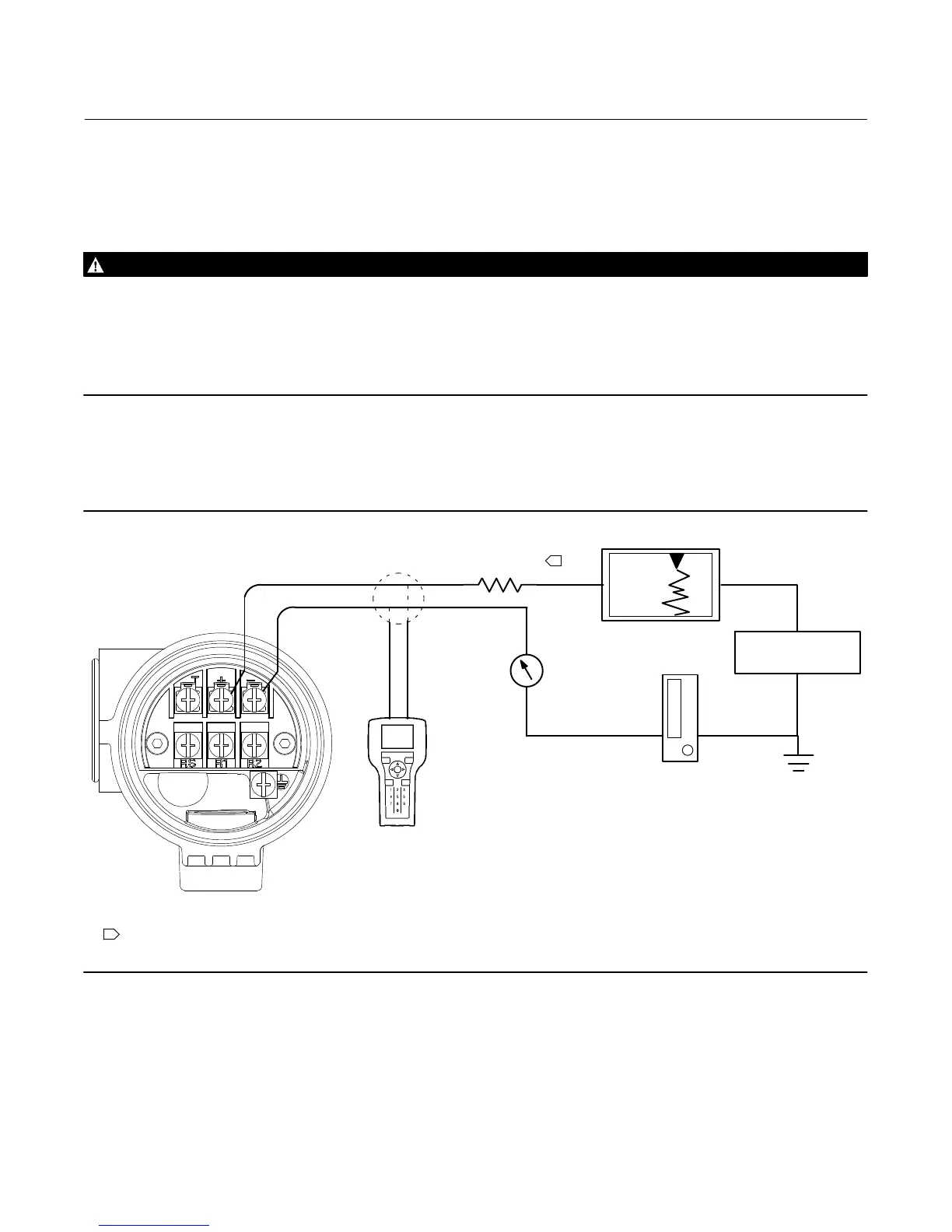
Proper electrical installation is necessary to prevent errors due to electrical noise. A resistance between 230 and 600
ohms must be present in the loop for communication with a Field Communicator. Refer to figure 9 for current loop
connections.
Figure 9. Connecting a Field Communicator to the Digital Level Controller Loop
230 R
L
600
POWER
SUPPLY
Signal loop may be grounded at
any point or left ungrounded.
A Field communicator may be
connected at any termination
point in the signal loop other
than across the power supply.
Signal loop must have between
230 and 600 ohms load for
communication.
Reference meter
for calibration
or monitoring
operation. May
be a voltmeter
across 250 ohm
resistor or a
current meter.
E0363
1
NOTE:
1 THIS REPRESENTS THE TOTAL SERIES LOOP RESISTANCE.
+
+
+
+
−
−
−
−
Power Supply
To communicate with the digital level controller, you need a 17.75 volt DC minimum power supply. The power
supplied to the transmitter terminals is determined by the available supply voltage minus the product of the total loop
resistance and the loop current. The available supply voltage should not drop below the lift‐off voltage. (The lift‐off
voltage is the minimum “available supply voltage” required for a given total loop resistance). Refer to figure 10 to

 Loading...


