Quick Start Guide
D103214X012
DLC3010 Digital Level Controller
February 2016
14
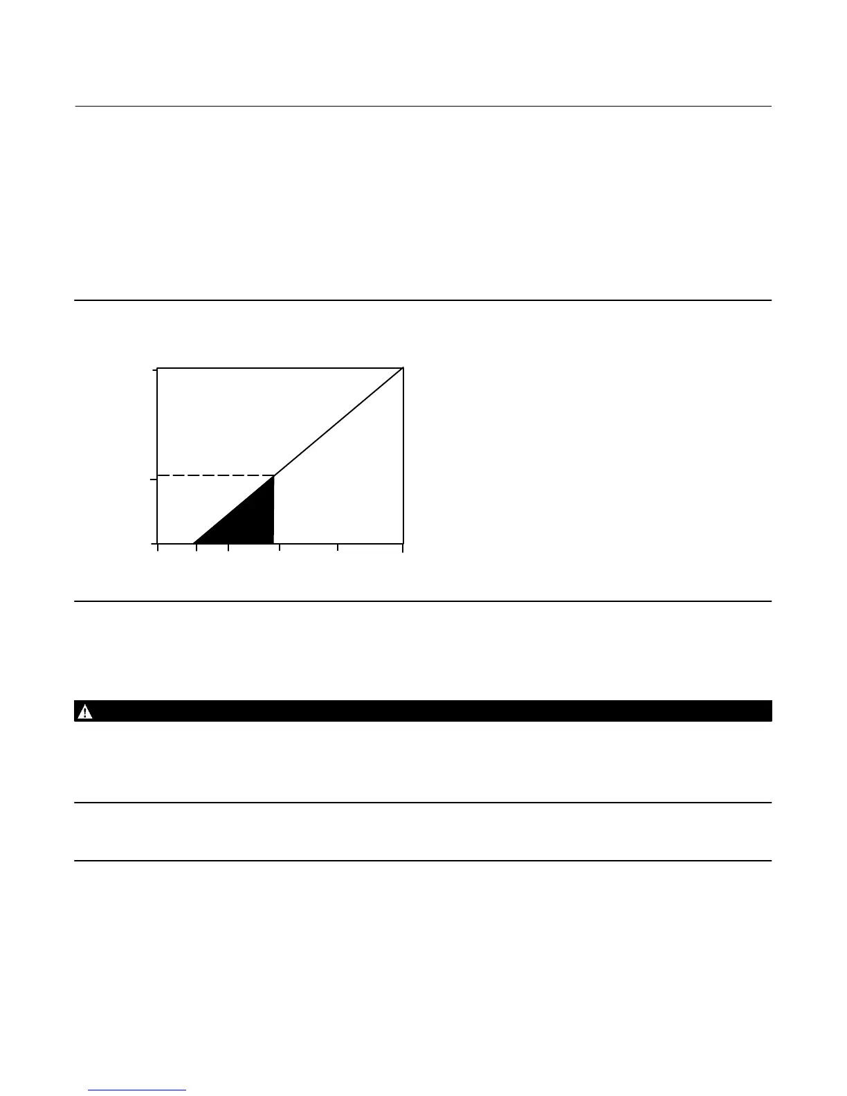
determine the required lift‐off voltage. If you know your total loop resistance you can determine the lift‐off voltage. If
you know the available supply voltage, you can determine the maximum allowable loop resistance.
If the power supply voltage drops below the lift‐off voltage while the transmitter is being configured, the transmitter
may output incorrect information.
The DC power supply should provide power with less than 2% ripple. The total resistance load is the sum of the
resistance of the signal leads and the load resistance of any controller, indicator, or related pieces of equipment in the
loop. Note that the resistance of intrinsic safety barriers, if used, must be included.
Figure 10. Power Supply Requirements and Load Resistance
Maximum Load = 43.5 X (Available Supply Voltage - 12.0)
12 30
LIFT‐OFF SUPPLY VOLTAGE (VDC)
Load (Ohms)
0
10 20 2515
783
250
Operating
Region
E0284
Field Wiring
WARNING
To avoid personal injury or property damage caused by fire or explosion, remove power to the instrument before removing
the digital level controller cover in an area which contains a potentially explosive atmosphere or has been classified as
hazardous.
Note
For intrinsically safe applications, refer to the instructions supplied by the barrier manufacturer.
All power to the digital level controller is supplied over the signal wiring. Signal wiring need not be shielded, but use
twisted pairs for best results. Do not run unshielded signal wiring in conduit or open trays with power wiring, or near
heavy electrical equipment. If the digital controller is in an explosive atmosphere, do not remove the digital level
controller covers when the circuit is alive, unless in an intrinsically safe installation. Avoid contact with leads and
terminals. To power the digital level controller, connect the positive power lead to the + terminal and the negative
power lead to the - terminal as shown in figure 11.
 Loading...


