Quick Start Guide
D103203X012
DVC2000 Digital Valve Controller
July 2017
7
Note
As a general rule, do not use less than 50% of the magnet array for full travel measurement. Performance will decrease as the array
is increasingly subranged.
The linear magnet arrays have a valid travel range indicated by arrows molded into the piece. This means that the hall sensor (on
the back of the DVC2000 housing) has to remain within this range throughout the entire valve travel. See figure 2.
The linear magnet arrays are symmetrical. Either end may be up.
There are a variety of mounting brackets and kits that
are used to mount the DVC2000 to different actuators.
However, despite subtle differences in fasteners,
brackets, and connecting linkages, the procedures for
mounting can be categorized as follows:
D Air‐to‐open sliding‐stem (linear) actuators
D Air‐to‐close sliding‐stem (linear) actuators
D Air‐to‐open 667 size 30i - 76i or Fisher GX actuator
D Air‐to‐close 657 size 30i - 70i or GX actuator
D Rotary actuators with travel up to 90 degrees
See figure 3 for the different travel feedback magnet
assemblies.
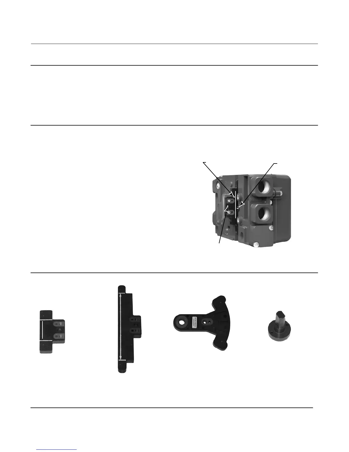
Figure 2. Travel Range
INDEX MARK
VALID TRAVEL RANGE
50 mm (2 INCH) SHOWN
MAGNET ASSEMBLY
(ATTACHED TO VALVE STEM)
W8830
Figure 3. Magnet Assemblies
RSHAFT END
ASSEMBLY 90 DEG
LINEAR
7, 19, OR 25 mm
(1/4, 3/4, 1 INCH)
LINEAR
38, 50, 110, OR 210 mm
(1‐1/2, 2, 4-1/8, OR 8-1/4 INCH)
ARCED
13 TO 30 DEGREE ROTATION

 Loading...


