Quick Start Guide
D103203X012
DVC2000 Digital Valve Controller
July 2017
9
6. Tighten the fasteners and remove the alignment template.
Note
Use a flat end hex key to tighten the magnet assembly fasteners to a torque of 2.37 N•m (21 in•lbf) for 4 mm screws, and
5.08 N•m (45 in•lbf) for 5 mm screws. For added security, especially in vibrating services, blue (medium) threadlocker may be
used on the fasteners.
7. Mount the digital valve controller to the mounting bracket, using the mounting bolts. See figure 6.
8. Check for clearance between the magnet assembly and the DVC2000 feedback slot. The magnet assembly should
be positioned so that the index mark in the feedback slot of the DVC2000 housing is within the valid range on the
magnet assembly throughout the range of travel. See figure 2.
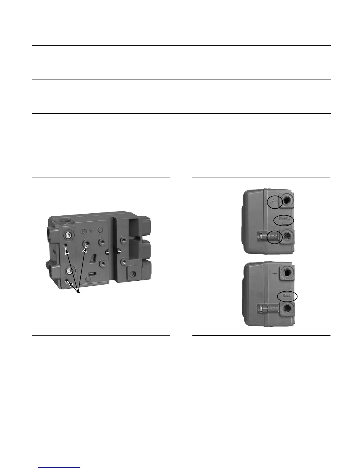
9. Install tubing between the actuator casing and the pneumatic positioner output connection that has the arrow
pointing away from the opening. See figure 7.
Figure 6. Mounting Holes for Linear Actuators
W9015
M8 THREADED
MOUNTING HOLES
Figure 7. Conduit and Pneumatic Thread Variations
W9016
ARROW P0INTING
AWAY FROM PORT =
OUTPUT TO ACTUATOR
ARROW P0INTING
TOWARDS THE PORT =
AIR SUPPLY IN
1/4 NPT
PNEUMATIC
CONNECTIONS
G1/4
PNEUMATIC
CONNECTIONS

 Loading...


