Quick Start Guide
D103203X012
DVC2000 Digital Valve Controller
July 2017
18
Basic Setup and Calibration
The local operator interface is available on all DVC2000 digital valve controllers. The interface consists of a liquid
crystal display, four pushbuttons, and a switch for position transmitter configuration. The DVC2000 is supplied with
one of three different language packs preinstalled, depending on the firmware revision and ordering option. Language
pack options are shown in table 1. To configure the language, follow the procedure outlined in the Basic Setup section.
The instrument must be powered with at least 8.5 volts and 3.5 mA to operate the local interface. Certain procedures
require up to 20 mA of current.
CAUTION
When accessing the terminals or pushbuttons, proper means of electrostatic discharge protection is required. Failure to
provide appropriate protection can cause the valve to move, resulting in valve/actuator instability.
Status Information
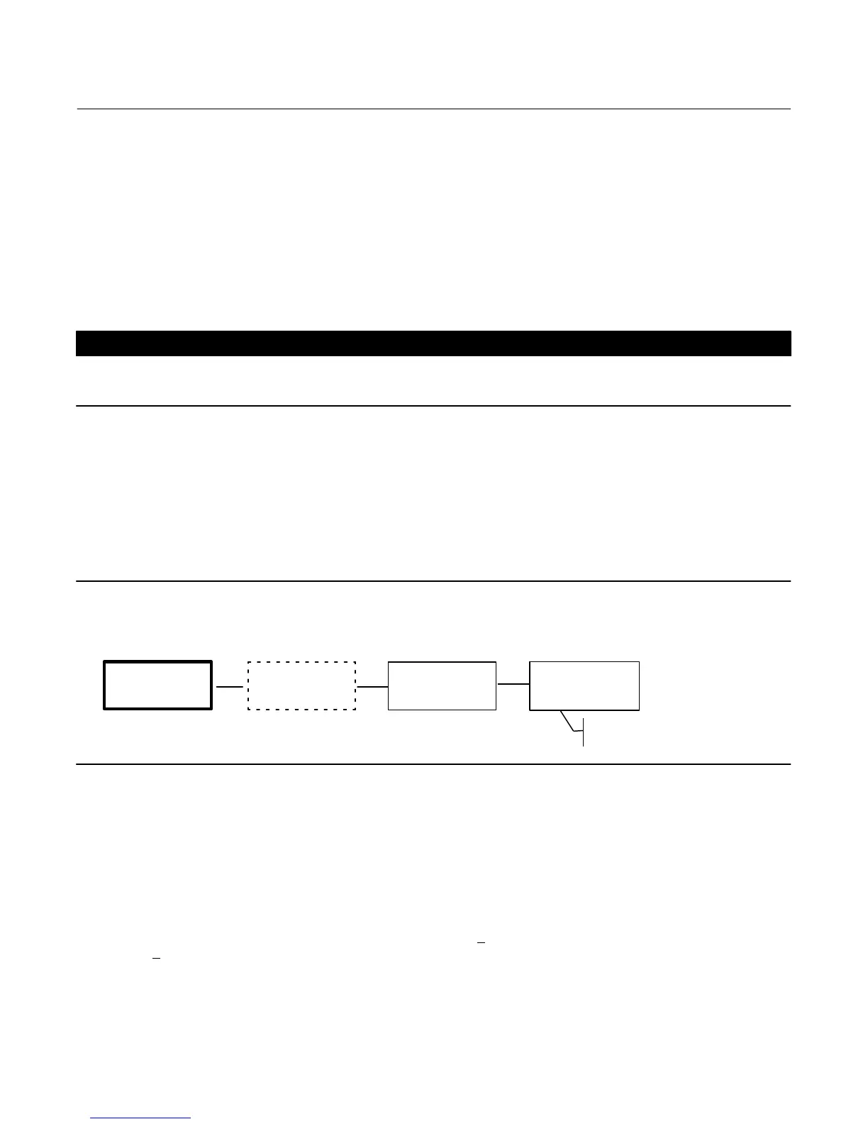
The first (home) screen on the LCD that is displayed after applying power to the instrument contains basic status
information. On an instrument that is calibrated and operating properly, the flow chart in figure 16 shows the available
information by pressing the right (") arrow key.
Figure 16. Home Screen on the LCD
Only with Optional
Transmitter / Limit Switches
TRAVEL = 66.8%
14.6 MA 0.92 BAR
SWITCH 1 = OPEN
SWITCH 2 = CLOSED
OFF
ON
PROTECTION
OFF
FW3:1, HW1:2
TUNING = C
"
A
"
A
"
A
TRAVEL=##.#%—Current valve travel in percent of calibrated travel.
##.# MA—Current input signal applied to the instrument in mA.
##.## BAR—Current pressure output to the actuator in the configured units (BAR, PSI or MPA).
SWITCH1—Current status of the optional limit switch wired to terminals +41 and -42.
SWITCH2—Current status of the optional limit switch wired to terminals +51 and -52.
FW#—Version of firmware running in the device.
HW#—Version of electronics hardware installed. The first number (#
: #) represents the main board, the second
number (# : #
) represents the secondary electronics.
TUNING = X—Current tuning set parameters configured in the device.
PROTECTION—Indicates whether the local interface is protected or not. With protection ON, the instrument cannot be
configured or calibrated with the local pushbuttons.
 Loading...


