32
A
B
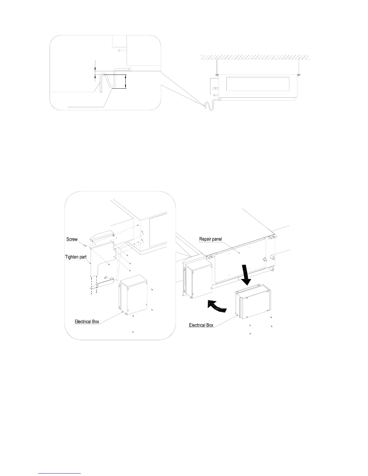
4). Refrigerant pipe insulation layer
To avoid condensation of drew and water leakage, gas pipe and liquid pipe of refrigerant should be
insulated with thermal insulation material and adhesive tape.
5). Install the Electrical Box. (Be Suit For 25KW~40KW)
In order to ease the maintaining work, we recommend to get of the electrical box part of the indoor unit to
refix it at the air outlet part. Please see following Fig 21.
Fig. 21 Schematic for the Electrical Box part
6). Install the wired remote controller
z A pit or a hole in the suitable position of the wall should be reserved for the connection signal cables.
z The connection wire between indoor unit and controller can be laid in the pit with 1# PVC pipe for
direct installation (Figure 22). For concealed installation, 1# PVC can also be utilized (Figure 23).
z Both Cable of direct installation and the concealed one, please drill two horizontal hole on the wall
and insert two wooden plug. Then fix the soleplate on the wall and insert the signal wire pin into the
plug as showed in Figure 24, finally fix the controller to the wall..
Water seal
Drain hose
 Loading...