11
LIQUID-COUPLED HEAT EXCHANGER ECONET
®
Installation & Maintenance Manual
11
FläktGroup DC_9010GB 20180327_R0 Specifications are subject to alteration without notice
ECONET
®
CONTROL AND ELECTRICAL INSTALLATION
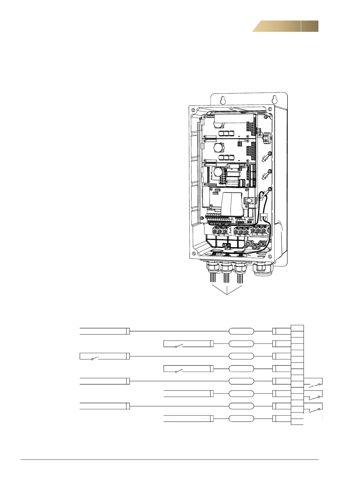
CONNECTING THE CONTROL SIGNALS
Connect the AHU controller signals to terminals according to
the illustration below.
The screening of control cables is necessary to comply with
the immunity levels given in the EMC Directive.
Control cables must be separated from motor and mains
cables. Terminal screws need to be tightened afterwards.
Control signals
Liquid flow signal 0-10 V is proportional to liquid flow in
ECONET system (0-max-flow).
7
2
11
8
9
11
10
11
32
33
41
42
51
52
12
14
IN 0-10VDC
Liquid flow signal Out 0-10 VDC
Control signal ground com GO 15
0-10 V signal Y 16
Common 11
C-type alarm 12
7
C NO 8
Control signal ground com GO 3
C NO 4
Common 13
F-A-type alarm 14
Common 9
P40 Indication 10
5
C NO 6
Control signal ground com GO 1
C NO 2
Cooling
P40. Indication
Functional A-type alarm
Component A-type alarm
Cooling recovery
Start
-RC1
 Loading...