LIQUID-COUPLED HEAT EXCHANGER ECONET
®
Installation & Maintenance Manual
24
FläktGroup DC_9010GB 20180327_R0 Specifications are subject to alteration without notice
ECONET
®
COMMUNICATION
In ECONET
®
there is available Modbus communication profile.
The following profile defines the communication interface when
integrating ECONET
®
into a larger automation system.
The purpose of this section is to provide users with the first
means to familiarize themselves with the configuration and use
of Modbus on ECONET
®
frequency inverter.
More information can be found from the following documents:
• Emotron Isolated RS232/485 2.0 Option. Instruction manual
• For the full specification of Modbus, refer to “Modicon Mod-
bus Protocol Reference Guide PI-MBU8-300 rev J”
The protocol used for data exchange is based on the Modbus
RTU protocol, originally developed by Modicon.
Physical connection can be either RS232 or RS485.
ECONET
®
acts as a slave with address 1 to 247 in a master-
slave configuration. This can be defined in parameter 2621.
Default is 1. The communication is half-dublex. It has a standard
non return zero (NRZ) format.
Baudrate can be set in parameter 2621. Default is 9600.
The character frame format (always 11 bit) has:
• One start bit
• Eight data bits
• One or two stop bits (ECONET use two stop bits)
• Even or no parity bit (ECONET use no parity)
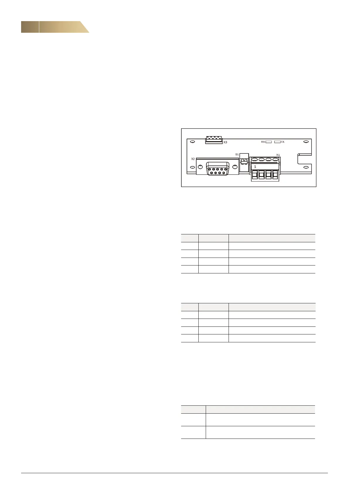
BOARD LAYOUT
Communication board is above control terminals.
USER CONNECTIONS
Terminal X1
Terminal X1 is used for RS485 communication.
D-Sub contact, X2
The D-Sub contact, X2, is used for RS232 communication
Switch S1
Switch S1 is used to terminate RS485-network.
LED
These LEDs can be used as simle status indications for
the bus systems.
X1 Name Function
1 Ground 0V reference
2 A-line Differential transmit and receive pin.
3 B-line Differential transmit and receive pin.
4 PE Protective earth
X2 Name Function
2 TX Transmit pin.
3 RX Receive pin.
4 Ground 0V reference
4 PE Protective earth
LED Description
RX Flashes when the node is receiving a message
transmitted on the bus.
TX Flashes when the node is transmitting a response
message to the master.
 Loading...