7
LIQUID-COUPLED HEAT EXCHANGER ECONET
®
Installation & Maintenance Manual
7
FläktGroup DC_9010GB 20180327_R0 Specifications are subject to alteration without notice
ECONET
®
ASSEMBLY AND INSTALLATION
UNPACKING
INSPECTION OF DELIVERED EQUIPMENT
– Check for signs of transit damage.
– Check that the product codes on the rating labels conform to
your requirement.
– Check the delivered components against the bill of material.
– The code for the pump unit (STAZ-74-…) can be found on the
ECONET
®
pump unit.
INSTALLATION INSTRUCTION
The following must be carried out on site by the plumbing/
automation and electrical contractors.
– Assembly of the pump unit, installation of pipes from the
exhaust and supply air coils, connection to the exhaust air
and supply air coils.
– Installation of necessary components for connecting an
external energy source, as set out in the documentation.
– Filling and air purging of system.
– Power supply to the ECONET
®
frequency inverter.
– Connection between the ECONET
®
frequency inverter and
the controller for the AHU.
– Wiring between the air flow sensor (supply air) and the
ECONET
®
frequency inverter.
OPTION
– Commissioning of the ECONET
®
system.
– Controls for AHU, SV 30, SV 50, etz.
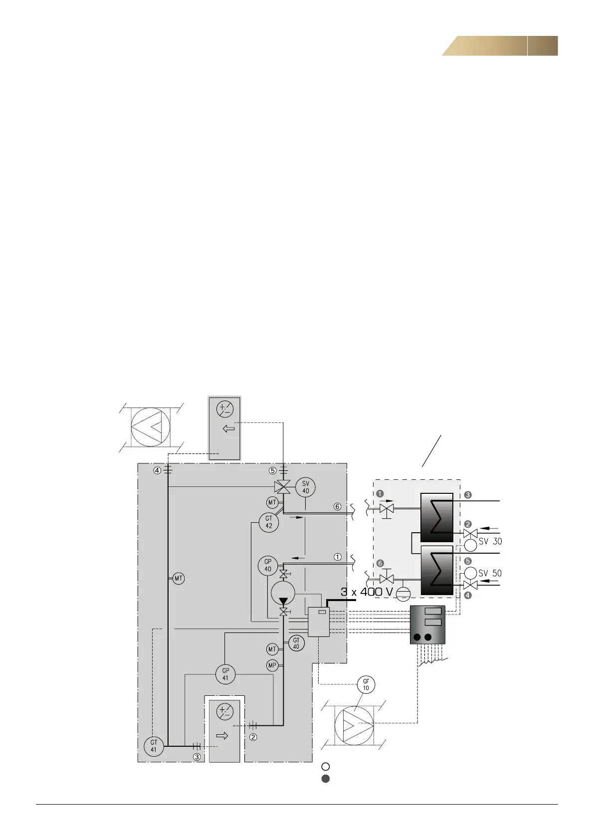
= Pipe connection: ECONET
®
= Pipe connection: Exchanger package
(EQRZ-05 ECONET
®
Exchanger Package, see separate manual).