LIQUID-COUPLED HEAT EXCHANGER ECONET
®
Installation & Maintenance Manual
10
FläktGroup DC_9010GB 20180327_R0 Specifications are subject to alteration without notice
ECONET
®
CONTROL AND ELECTRICAL INSTALLATION
POWER SUPPLY CONNECTIONS
The inverter must be connected via disconnecting switches.
Main power shall be 3x400 VAC. An electrician shall dimen-
sion the fuses for the pump according to the table below, and
according to the site circumstance and local standards. See
frequency inverter instructions for fuse and cable dimen-
sioning. Terminal screws need to be tightened afterwards.
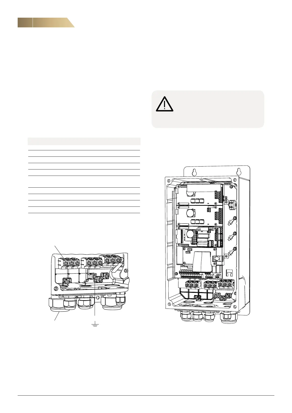
Connect L1, L2, L3 power supply cable, 3x400 VAC, to terminals
and protective earth (PE). Observe proper grounding methods
as described in the frequency inverter product manual.
AHU SiZE PUMP OUTPUT MAX. CURRENT
005 0.37kW 0.96 A
008,009 0.55 kW 1.44 A
011,014,018,020 0.7 kW 1.9 A
023,027 1.1 kW 2.55 A
032,036 1.5 kW 3.15 A
041,045,050,054,
056,063,068 2.2 kW 4.45 A
072 3.0 kW 6.35 A
079,090,108 4.0 kW 8.0 A
126,135,144,158,180 5.5 kW 11.2 A
210 7.5 kW 15.2 A
Table 1 Single pump max. currents. Pump data due to the size
of the air-handling unit. The fuse size depends on site-specific
circumstances and must be dimensioned by an electrician.
L1
L2
L3
DC-
DC+
R
U
V
W
Power supply terminal
Cable gland
for power
supply cable
PE
Warning!
Ensure that all wiring is electrically insulated
and cannot be made “live” unintentionally by
other personnel.
 Loading...