LIQUID-COUPLED HEAT EXCHANGER ECONET
®
Installation & Maintenance Manual
14
FläktGroup DC_9010GB 20180327_R0 Specifications are subject to alteration without notice
ECONET
®
FUNCTIONAL DESCRIPTION
FUNCTION
The heat recovery function is controlled by the ECONET
®
fre-
quency inverter. The specific functions for the AHU must be
controlled by a separate controller (not included in the ECONET
®
delivery). The functions below describe the internal heat reco-
very function for ECONET
®
. The process and instrumentation
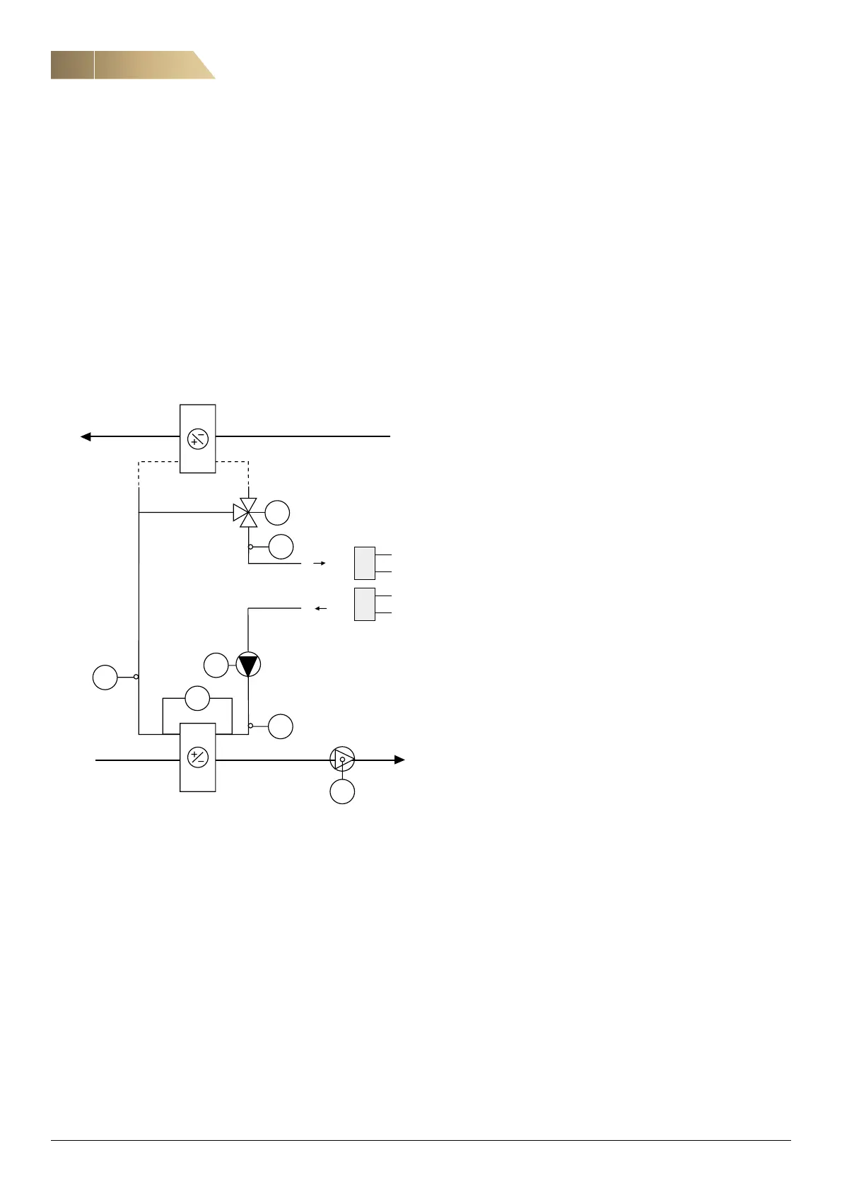
diagram for ECONET
®
is shown below.
DELIVERY
GT40, GT41, GT42, SV40, GP41, GF10, FO40, P40.
AIR HANDLING UNIT NOT RUNNING
When the temperature GT41 is below +16°C, the pump will start
to operate at a constant low speed. When the liquid tempera-
ture GT41 is higher than +17°C, the pump P40 will stop.
START OF THE AIR HANDLING UNIT
When ECONET
®
receives a start-up signal, the pump P40 starts
to operate at a constant high speed after 3 minutes. After that
the pump goes to optimal sequence.
MAIN FUNCTION
ECONET
®
is a part of the sequence to control the supply air
temperature to its set point.
GT
42
GP
41
GT
41
GT
40
GF
10
FO
40
Exhaust air
Supply air
Supplementary
energy
SV
40
Main functions of ECONET® frequency inverter (control
sequence):
• Cooling recovery, On/Off signal
The pump P40 and frequency inverter FO40 regulate the
liquid flow to an optimal value for cooling recovery and valve
SV40 by-pass will then close. NOTE. The heat recovery
signal must be 0 %.
• Supplementary cooling, On/Off signal
The pump P40 and frequency inverter FO40 regulate the
liquid flow to the optimal value for supplementary cooling.
SV40 will open. NOTE. The heat recovery signal must be 0 %.
• Heat recovery, 0...100 %, 0..10 V signal
The pump P40 starts at minimum speed, the valve SV40
moves from open to closed, pump P40 goes from minimum
speed to optimal speed (optimal heat recovery liquid flow).
FROST AND ICE PROTECTION
• Frost protection: Protection against frost formation on
the exhaust air coil (air side).
The liquid temperature at GT41 is prevented from dropping
below the temperaure (approx.-3 °C) for frost protection by
regulating the liquid flow with the pump P40 and FO40 from
optimal liquid flow to an increased liquid flow.
• Risk of frost formation
When the liquid temperature GT41 falls below the A alarm
value (approx. -10 °C), the A-type functional alarm is given.
• Ice protection: Protection against ice formation in the heat
exchangers for supplementary heating/cooling (water side).
The liquid temperature at GT42 is prevented from dropping
below the temperature (approx. 6 °C) for ice protection by
regulating the liquid flow with the pump P40 and FO40 from
optimal liquid flow to an increased liquid flow.
• Risk of ice formation
When the liquid temperature GT42 falls below the A alarm
value (approx. 2 °C), the A-type functional alarm is given.
ALARMS
When A-alarm is generated, AHU must be stopped
immidiatly. B-alarms are only shown in display.
• Functional A-type alarms
– Risk of frost formation, GT41 ( - 10° C)
– Risk of ice formation, GT42 (+ 2 °C)
– Low pressure in ECONET
®
liquid circuit
• Component A-type alarms
– Signal out of range (GT 41, GT 42)
– Pump alarm
– Power supply is missing
• B-type alarms
– GT 40 signal out of range
– Bypass valve not working (SV 40)
– Liquid flow alarm
 Loading...