15
LIQUID-COUPLED HEAT EXCHANGER ECONET
®
Installation & Maintenance Manual
15
FläktGroup DC_9010GB 20180327_R0 Specifications are subject to alteration without notice
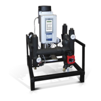
OPERATION VIA THE CONTROL PANEL
GENERAL
The control panel displays the status of the frequency inverter
and is used to set all the parameters. It is also possible to con-
trol the motor directly from the control panel.
THE CONTROL PANEL
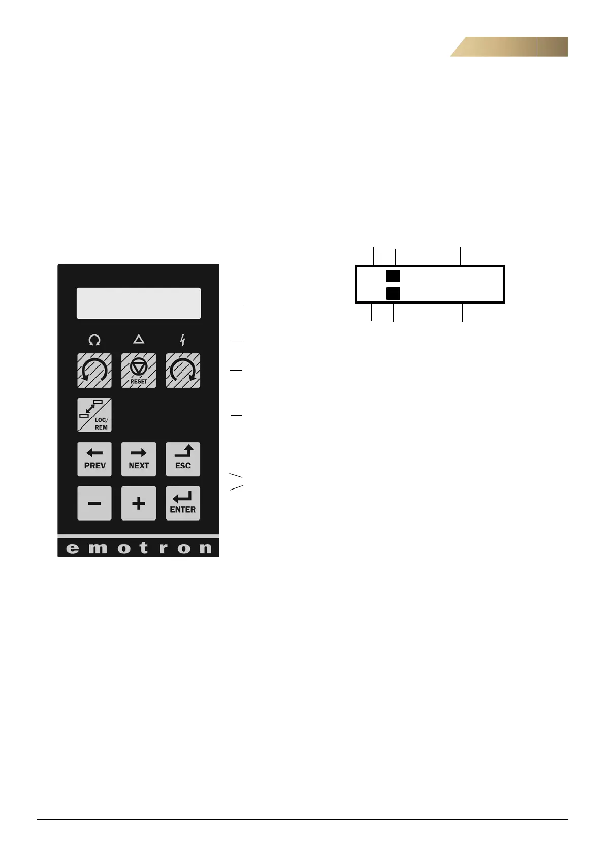
THE DISPLAY
The display is back lit and consists of 2 rows, each with space
for 16 characters. The display is divided into six areas.
The different areas in the display are described below
Area A: Shows the actual menu number (3 or 4 digits).
Area B: Shows if the menu is in the toggle loop or the frequency
inverter is set for Local operation.
Area C: Shows the heading of the active menu.
Area D: Shows the status of the frequency inverter (3 digits).
The following status indications are possible
Acc: Acceleration
Dec: Deceleration
I2t: Active I2t protection
Run: Motor runs
Trp: Tripped
Stp: Motor is stopped
VL: Operating at Voltage limit
SL: Operating at Speed limit
CL: Operating at Current limit
TL: Operating at Torque limit
OT: Operating at Temperature Limit
LV: Operating at Low Voltage
Sby: Operating from Standby power supply
SST: Operating Safe Stop, is blinking when activated
Area E: Shows active parameter set and if it is a motor
parameter.
Area F: Shows the setting or selection in the active menu.
This area is empty at the 1st level and 2nd level menu.
This area also shows warnings and alarm messages.
LC Display
LEDs
Control Keys
Toggle Key
Function Keys
B
221 Motor Volt
Stp M1: 400V
T
A
 Loading...