PAGE 13Help: 888-426-5001 QualityWaterForLess.com
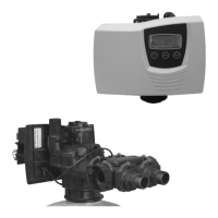
3) Locate the brine well and remove the cap.
You
may also take this moment to prepare and
insert the brine support grid determined
from pages 6 and 7
. Then pull the
474 Brine
Float Assembly
out of the brine well as shown
in Figure 13-A
4) Next, fix the 474 Brine Float Assembly to the
brine well through the pre-drilled hole and
hand-tighten as shown in Figure 13-B
fIGure 13-bfIGure 13-a
fIGure 13-c
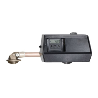
5) Take the other end of your brine line tube, make
sure this end is clean cut, recut if it is not clean,
mark 3/4” from the end of the tube, and insert the
tube through the small hole drilled through the brine
tank and brine well (Figure 13-C)
6) Firmly insert the tubing end 3/4” into the tube
opening on the 474 Brine Float Assembly as
shown in Figure 13-D. i
Make sure the tube is
fully inserted into the assembly
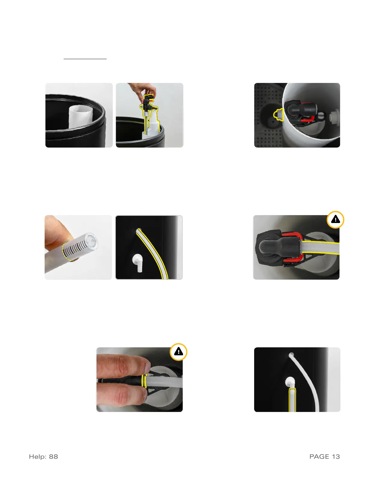
7) If you ever need to remove the tube, evenly press on
both sides of the grey ring surrounding the tube and
pull out as shown in Figure 13-E. i
Be sure to recut
the end of the tube each time you remove it to
ensure a proper seal when the tube is inserted
8) Finally, use ½” inner diameter (I.D.) tubing to connect
the drain barb fitting on the brine tank to a floor drain
as shown in Figure 13-F. Note that this is not neces-
sary as the 474 assembly is designed to prevent an
overflow from occuring, but it is a good precaution
fIGure 13-d
fIGure 13-e fIGure 13-f
 Loading...