Home
Flexim
Measuring Instruments
FLUXUS F704**-A2 Series
Flexim FLUXUS F704**-A2 Series User Manual
4
of 1
of 1 rating
192 pages
Give review
Manual
Specs
To Next Page
To Next Page
To Previous Page
To Previous Page
Loading...
FLUXUS F70x
5 Selection of the Measuring Point
24
UMFLUXUS_F7V4-6-2EN, 2017-
10-01
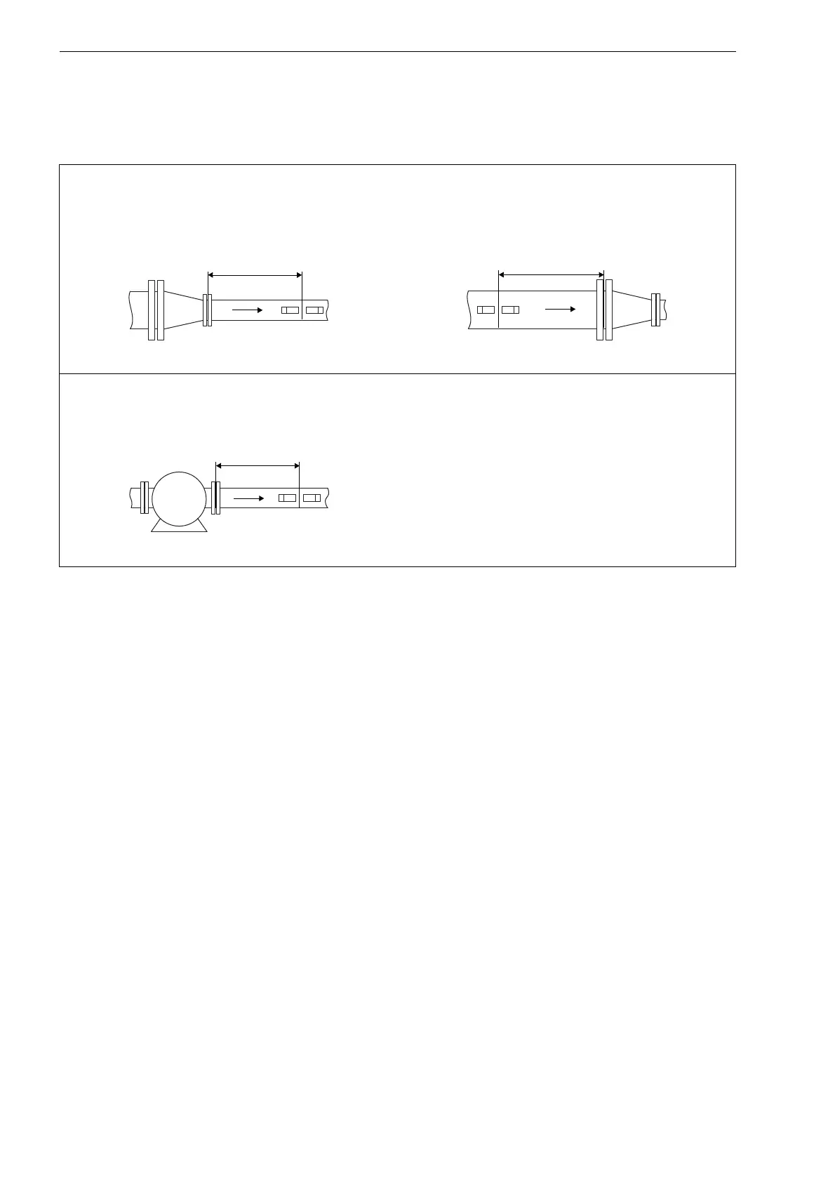
disturbance source: reducer
inlet: l
≥
10 D
outlet: l
≥
5 D
disturbance source:
pump
inlet: l
≥
20
D
Tab. 5.2:
Recommended distance from disturbance sources;
D – nominal pipe diameter at the measuring point,
l – recommended distance between disturba
nce sour
ce and transducer position
l
l
l
p
23
25
Table of Contents
Default Chapter
5
Table of Contents
5
1 Introduction
9
Regarding this User Manual
9
Safety Instructions
9
Warranty
9
2 Handling
10
First Inspection
10
General Precautions
10
Cleaning
10
3 General Principles
11
Measurement System
11
Measurement Principle
11
Measurement Arrangements
15
4 Description of the Transmitter
18
Design of FLUXUS F704
18
Design of FLUXUS F705
18
Design of FLUXUS F706
19
Design of FLUXUS F709
19
Keyboard
20
5 Selection of the Measuring Point
21
Acoustic Penetration
21
Undisturbed Flow Profile
23
Selection of the Measurement Arrangement Taking Onto Account the Measuring Range and the Measuring Conditions
25
Selection of the Sound Beam Plane Near an Elbow
27
6 Installation
28
Location
28
Transmitter FLUXUS F704, F705, F706
28
Transmitter FLUXUS F709
30
Transducers
31
Temperature Probe
46
7 Connection
49
Transducers
53
Temperature Probe
68
Power Supply
75
Outputs
77
Inputs
80
Serial Interface
83
Sensor Module (SENSPROM)
84
SD Card (Optional)
86
8 Start-Up of the Transmitter
87
Switching on
87
Initialization
87
Display
87
Hotcodes
89
Language Selection
90
Operation State Indication (FLUXUS F709)
90
Interruption of the Power Supply
90
9 Basic Measurement
91
Input of the Pipe Parameters
91
Input of the Medium Parameters
93
Other Parameters
94
Selection of the Channels
95
Defining the Number of Sound Paths
95
Transducer Distance
95
Start of the Measurement
97
Detection of the Flow Direction
97
Interruption of the Measurement
97
10 Displaying the Measured Values
98
Selection of the Physical Quantity and of the Unit of Measurement
98
Toggling between the Channels
98
Adjustment of the Display
99
Status Line
100
Transducer Distance
100
11 Advanced Measuring Functions
101
Damping Factor
101
Totalizers
101
Settings of the Hybridtrek Mode
102
Upper Limit of the Flow Velocity
103
Cut-Off Flow
104
Uncorrected Flow Velocity
104
Measurement of Highly Dynamic Flows (Fastfood Mode)
105
Calculation Channels
105
Change of the Limit for the Inner Pipe Diameter
108
Remote Functions
108
Program Code
111
12 Data Logger and Transmission of Data
112
Data Logger
112
Transmission of Data
115
13 Libraries
121
Partitioning of the Coefficient Memory
121
Input of Material/Medium Parameters Without the Extended Library
122
Extended Library
123
Deleting a User-Defined Material/Medium
126
Arrangement of the Material/Medium Scroll List
127
14 Settings
129
Time and Date
129
Dialogs and Menus
129
Measurement Settings
132
Setting the Contrast
133
Instrument Information
133
15 Superuser Mode
134
Activation/Deactivation
134
Transducer Parameters
134
Defining the Flow Parameters
134
Limit of the Signal Amplification
136
Upper Limit of the Sound Speed
136
Detection of Long Measurement Failures
137
Number of Decimal Places of the Totalizers
137
Temperature-Based Heat Flow Cut-Off
138
Manual Reset of the Totalizers
138
Display of the Sum of the Totalizers
138
Display of the Last Valid Measured Value
139
Display During the Measurement
139
16 Heat Flow Measurement
140
Calculation of the Heat Flow Rate
141
Normal Measuring Mode
141
BTU Mode
142
Measurement
144
Two Independent Heat Flow Rate Measurements
145
Steam in the Supply Line
145
17 Inputs
147
Binary Inputs
147
Analog Inputs
147
18 Outputs
150
Installation of an Output
150
Error Value Delay
154
Activation of an Analog Output
154
Configuration of a Frequency Output as a Pulse Output
155
Activation of a Binary Output as a Pulse Output
156
Activation of a Binary Output as an Alarm Output
157
Behavior of the Alarm Outputs
159
Deactivation of the Outputs
161
19 Troubleshooting
162
Problems with the Measurement
163
Selection of the Measuring Point
163
Maximum Acoustic Contact
164
Application Specific Problems
164
Large Deviations of the Measured Values
164
Problems with the Totalizers
165
Problems During the Heat Flow Measurement
165
Data Transmission
165
A Menu Structure
166
B Units of Measurement
181
C Reference
186
D Declarations of Conformity
190
4
Based on 1 rating
Ask a question
Give review
Questions and Answers:
Need help?
Do you have a question about the Flexim FLUXUS F704**-A2 Series and is the answer not in the manual?
Ask a question
Flexim FLUXUS F704**-A2 Series Specifications
General
Brand
Flexim
Model
FLUXUS F704**-A2 Series
Category
Measuring Instruments
Language
English
Related product manuals
Flexim FLUXUS F704**-NN Series
192 pages
Flexim FLUXUS F704**-F2 Series
192 pages
Flexim FLUXUS F705**-NN Series
192 pages
Flexim FLUXUS F501
146 pages
Flexim FLUXUS G809
181 pages
Flexim FLUXUS F801
160 pages
Flexim FLUXUS G608
244 pages
Flexim FLUXUS G704
257 pages
Flexim FLUXUS ADM 8027
160 pages
Flexim FLUXUS F809 F1 Series
186 pages
Flexim FLUXUS F808 F1 Series
186 pages
Flexim FLUXUS ADM 7 07 Series
87 pages