Aircraft Type: CTSW
FLIGHT DESIGN
Aircraft Operating Instructions
Page: 7-3
AU 010 01000
Rev. No: 7
Original Issue Date: 28-Feb-2005
Revision Date: 29-Apr-2008
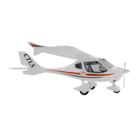
Located on the plate of the electric mechanism MT-10 is the limit switch which has
the function to limit the movement of flaps. This corresponds to the maximum up
deflection. When the flaps move, the LED display VD2 illuminates.
c) When the movement of flaps has been accomplished, the control switch should be
reset to a neutral position (see item 1, a).
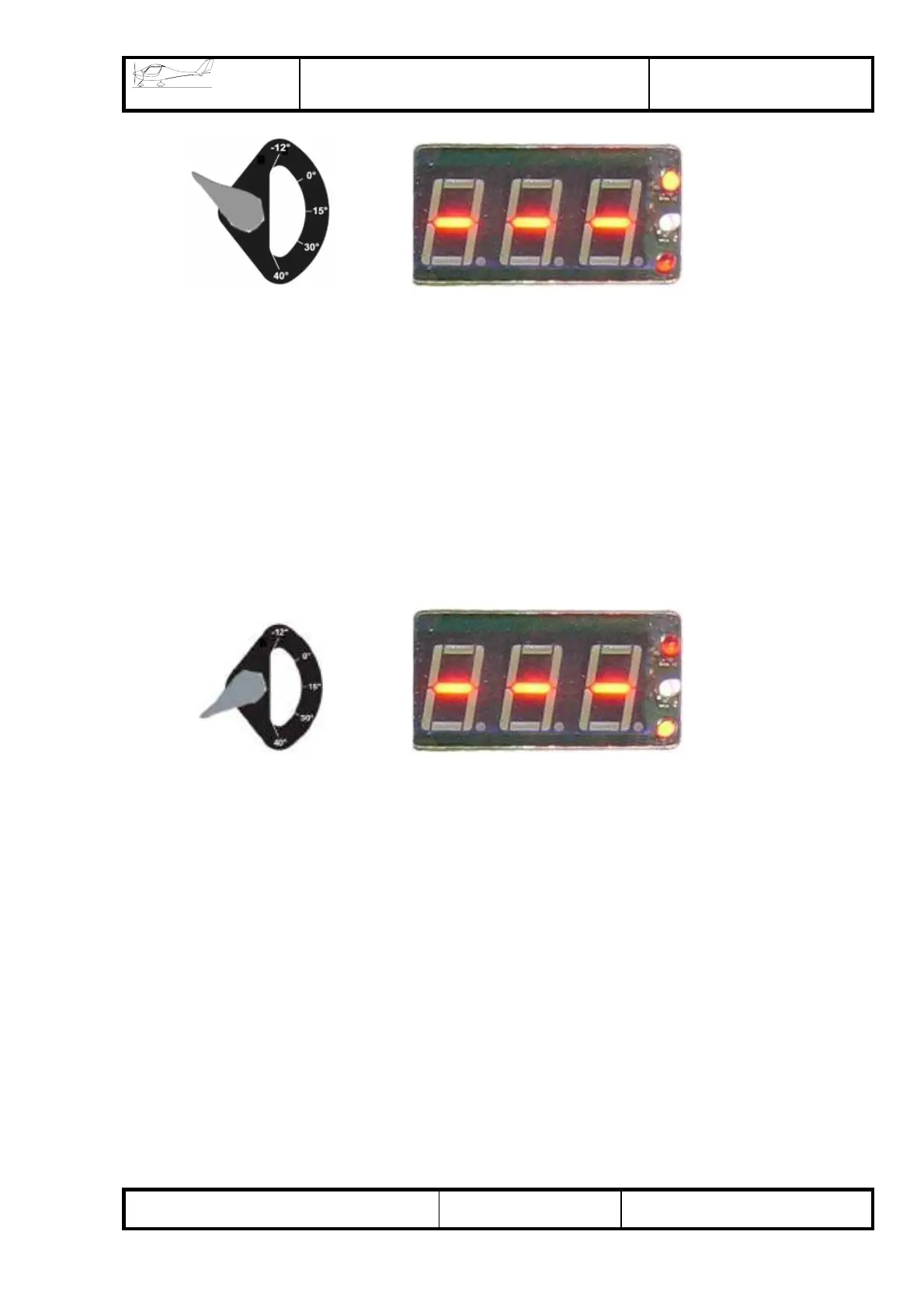
d) When the flap control switch is turned by 180° with reference to 0° position, the
flaps start to extend (flaps move down).
At this point, the LED display VD3 illuminates. The limit switch located on the MT-10
has the function to limit the movement of flaps.
e) Intermediate flap position (for instance 0°, 15°, 30°) is to be selected by sight
according to the position of flaps with respect to the wing.
To set the flaps in intermediate positions, if necessary, ensure that flaps move up or
down as far as the required position. After that, stop the movement of flaps by setting
the flap control switch in a neutral position (item 1, a).
2) To activate the automatic operation, set the switch in one of the designated
positions (-6° (-12°), 0°, 15°, 30°, 40°), accompanied by an indication at the display
corresponding to the selected position. The movement of flaps in these positions is to
be stopped automatically.
To change the settings of the automatic operation, if necessary, comply with the
instructions “Setting-up of flap positions”.
VD2
VD3