EN-US English
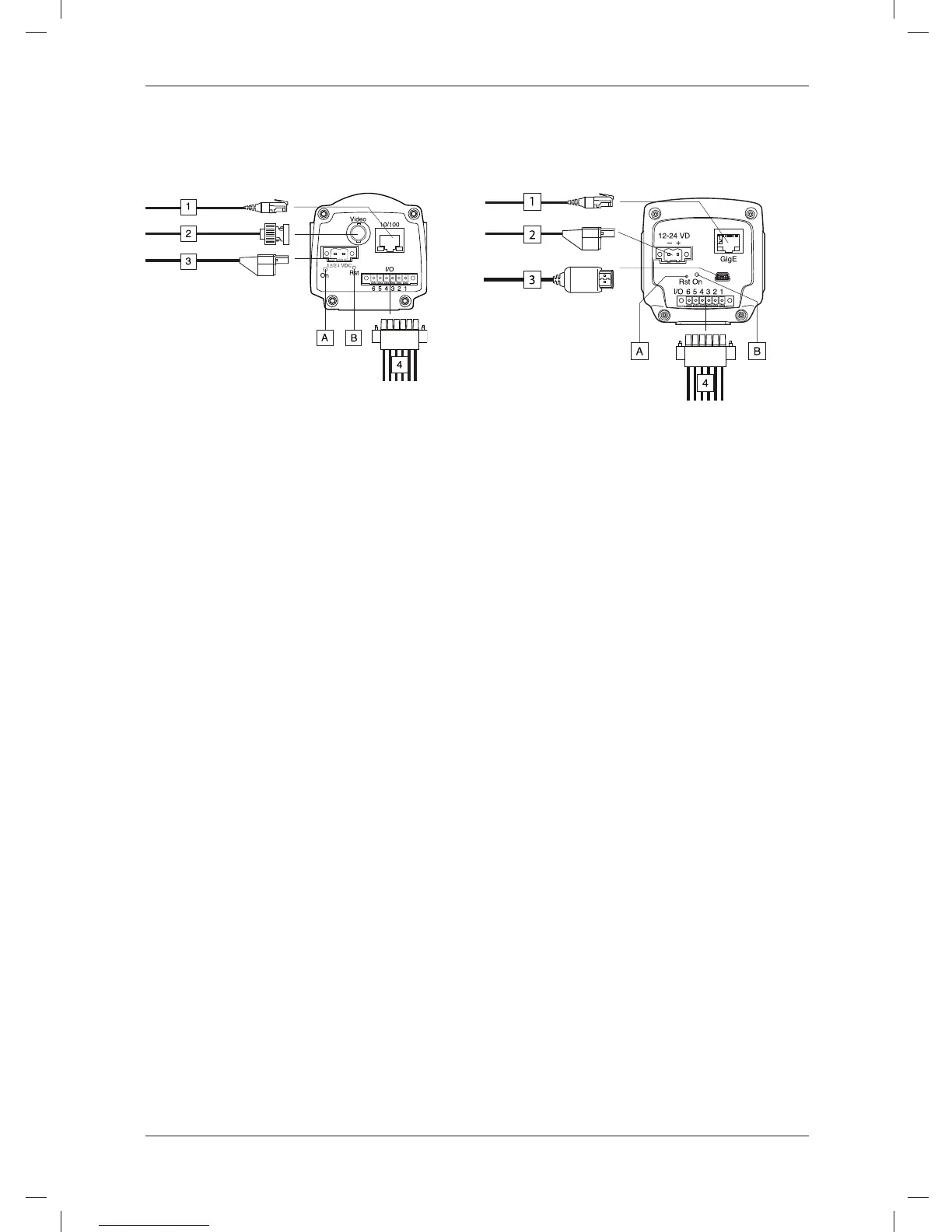
Step 3a: Connecting the Step 3b: Connecting the
camera (FLIR A3XX) camera (FLIR A6XX)
Figure Figure
Callouts
Callouts
1. Network cable with an RJ45 connec-
1. Network cable with an RJ45 connec-
tor for Ethernet connectivity and
tor for Ethernet connectivity and
PoE™ (dependent on the camera
PoE™ (dependent on the camera
model).
model).
2. Video cable with a BNC connector for
2. Power cable for 12–24 VDC power in.
CVBS (composite video) output (de-
3. USB cable with a USB mini-B con-
pendent on the camera model).
nector for control and image transfer.
3. Power cable for 12–24 VDC power in.
4. Digital I/O ports, opto-isolated (six-
4. Digital I/O ports, opto-isolated (six-
pole screw terminal).
pole screw terminal).
(A) Hardware reset button (for a factory
(A) Power indicator.
default reset).
(B) Hardware reset button (for a factory
(B) Power indicator.
default reset).
See also
See also
For complete information on indicator
For complete information on indicator
signals and pin configurations, see the
signals and pin configurations, see the
documentation on the User
documentation on the User
Documentation CD-ROM.
Documentation CD-ROM.
Step 4: Finding and
detecting cameras in a
network using FLIR IP
Config
General
Before you start working with the
cameras, you need to detect which
cameras are available in the Ethernet
network. You may also want to change
© 2011, FLIR Systems, Inc. All rights reserved worldwide.
19
Publ. no. T559492, rev. 010
 Loading...