Technical data9
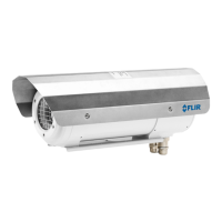
9.4 FLIR A310 ex 45°
P/N: 71001-1104
Rev.: 17787
Introduction
The FLIR A310 ex is an ATEX-proof solution, with a thermal imaging camera mounted in
an enclosure, making it possible to monitor critical and other valuable assets in explosive
atmospheres. Process monitoring, quality control, and fire detection in potentially explo-
sive locations are typical applications for the FLIR A310 ex.
• Thermographic monitoring and early fire detection in explosion–hazard area.
• Enclosures for infrared cameras in Ex zones 1, 2, 21, and 22.
• ATEX certified.
• Protection class IP67.
• Plug and play installation, enclosure is delivered ready-for-use.
• Available with additional options.
The certification comprises the whole system, which includes the enclosure as well as all
components built inside of it, such as the infrared camera, heater, and integrated control-
ler. This means that no additional certification is required for operation.
The integrated controller is equipped with two fiber optic and two Ethernet ports. This en-
ables a flexible network integration in star ring topologies.
Furthermore, the integrated controller features several digital I/O channels and sensors
for temperature, humidity, and pressure. Among other functions, the I/O channels enable
the user to switch on/off the camera and the heater via remote control. Access is accom-
plished through an integrated web interface or Modbus TCP/IP.
Explosion-proof housing
General data
Ambient temperature range for operation –20°C to +40°C
Protection class IP67
Weight 6.7 kg (without camera and lens)
Empty volume 5.06 l
External dimensions (without sun shield) D = 170 mm, L = 408 mm
Housing material Nickel-plated aluminium
Surface Powder coated
Protection window
Germanium, double-sided AR Coated, externally
with additional hard-carbon layer
Maximum power of the additional heater 16 W
Operating voltage 24 V DC
Maximum electric connection power 60 W
Power cable Helukabel 37264
Length of power cable 4 m (13 ft.)
Power cable configuration Pigtail
Integrated controller 4-port switch with 2 × fiber-optic LC 100Base-FX
or 2 × RJ45(10/100) up-links, ring-topology sup-
port for reduced cabling effort, 2 × internal tem-
perature sensors, air humidity and pressure
sensor, digital output module controllable via
Modbus TCP/IP or web interface to enable turning
the heater on/off
Ethernet medium
Multi-mode breakout fiber AT-V(ZN)Y(ZN)Y 4G50/
125 OM2
Length of Ethernet cable 4 m (13 ft.)
Ethernet configuration Pigtail with FC connector
#T559891; r.18204/18204; en-US
26