5 –Camera Controller
A6000 and A8500 Series User’s Manual
60
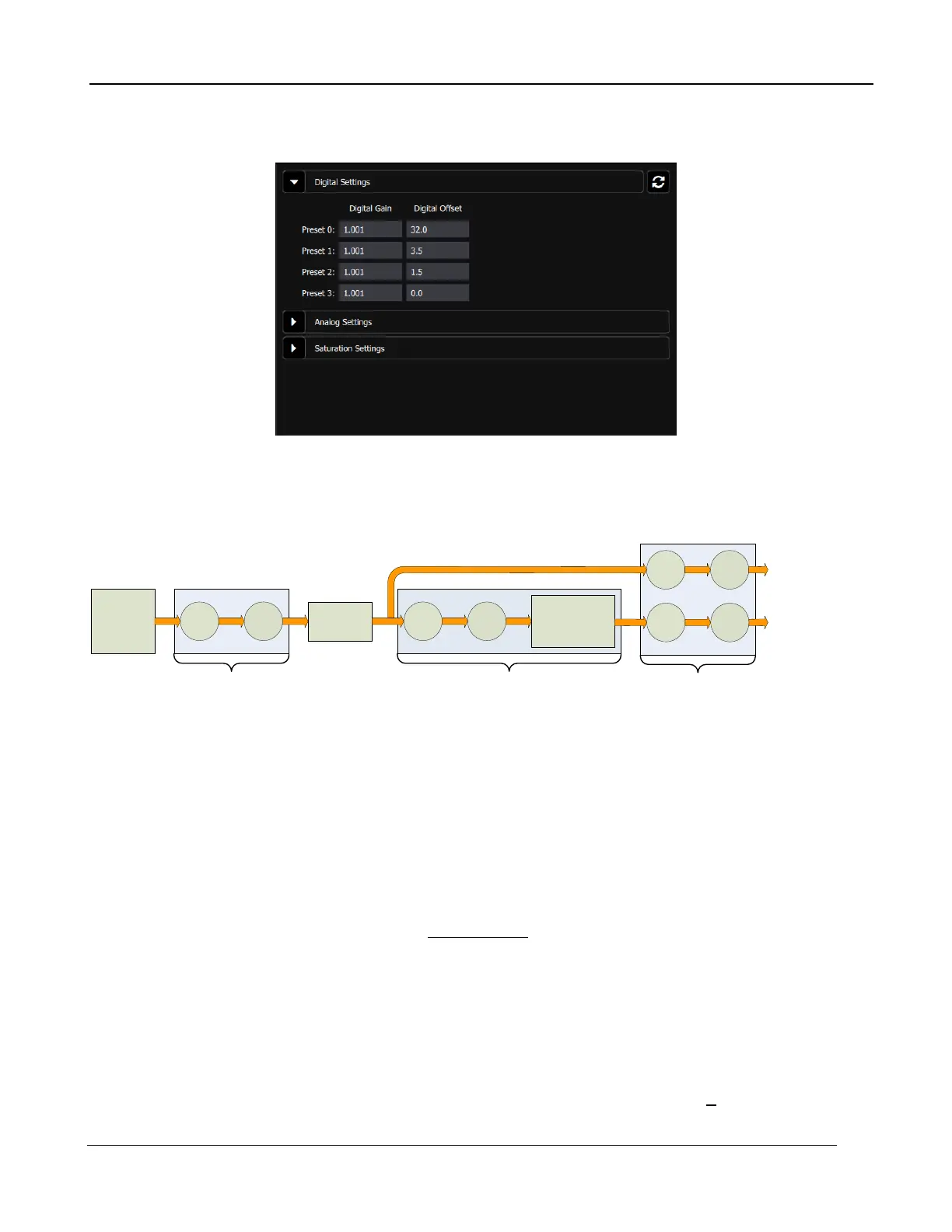
If a preset does not have a factory calibration loaded, then it is possible to edit these values, as shown
below:
The digital gain and offset stages are digital features of the camera that allow the corrected digital
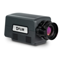
output of the camera to be mapped to different output ranges. The following diagram illustrates the
position of these stages in the signal path:
x
Detector 14-bit A/D
+
Digital
Gain/Offset
x +
NUC Table
Bad Pixel
Replacement
Algorithm
Corrected Data
Uncorrected Data
x +
Analog
Gain/Offset
x +
A-Series Signal Processing Chain
The analog FPA data is passed through an analog gain and offset stage that are factory-set to ensure
that the entire range of the FPA output is matched to the A/D input. This is shown in the figure below,
which plots the digital output of a typical camera against background photon flux. The actual scale of
the flux depends on integration time setting. The figure shows an example where the user desires to
operate the camera between two flux points such that these two limits use the entire 14-bit range.
With no global gain and offset adjustment these two points correspond to 3200 counts and 15800
counts for the low and high flux ranges respectively. Having obtained these numbers, we set the gain
to use the full 14-bit range:
30.1
320015800
16383
=
−
=gain
Since the offset stage is after the gain stage, we calculate the offset value using the gain:
41603200 −=−= gainoffset
These values are then entered into the global gain and offset controls and the linearized (red curve)
transfer function shown is the result.
The available gain range is 1.999 to essentially zero; the available offset range is + 32,767. The
default values are a gain of 1 and an offset of zero. Because the system sensitivity (NET) is set prior