6 – Interfaces
A6000 and A8500 Series User’s Manual
76
6.5.5 Sync In [All except A6705 and A858x]
The Sync In can be selected, by the user, to operate as an external clock. It is a rising edge TTL
signal (5.5V max). The minimum width is 160nS. Nominal operating voltage is 0 to 5.5V. The
absolute maximum range is -0.5V to 6.5V. Vih=2V, Vil=0.8V. Vih is the minimum voltage at which the
camera will interpret the signal as a “high” and Vil is the maximum voltage at which the camera will
interpret the signal as a “low”.
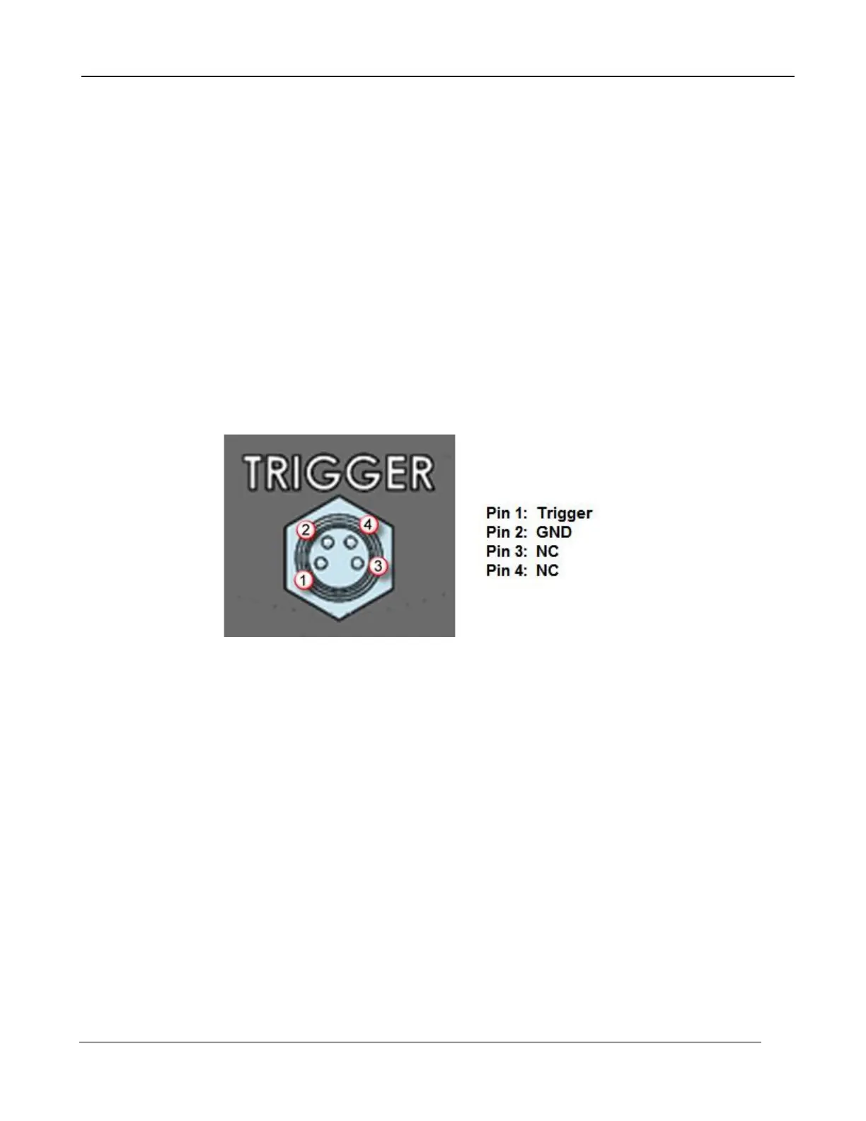
6.5.6 Trigger In [A6705 only]
The A6705 has a trigger input that allows an external signal to control when images are generated.
One image is generated for each trigger event. The trigger is designed to accept a 24V (max) signal.
>18V is considered “high” and less than 10V is considered “low”. The trigger can be configured to
look for a rising or falling edge. The connector is an industrial standard M8-4. The pin out is shown
below.
The trigger is opto-isolated, ESD protected, and reverse polarity protected