6 – Interfaces
A6000 and A8500 Series User’s Manual
75
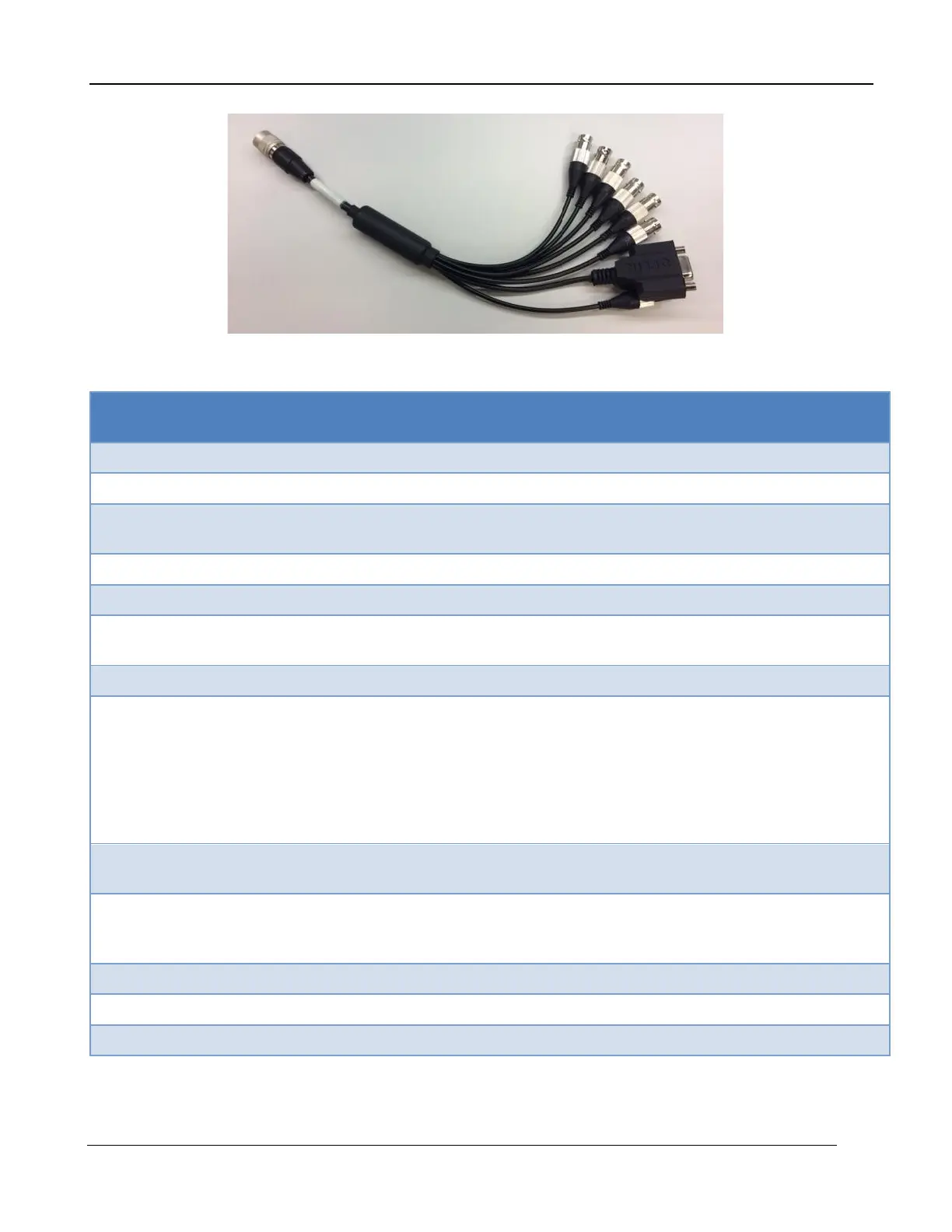
The provided breakout cable has numerical markings on the BNC overmolding that are described in
the table below.
Sets RecordStart bit in image header. Can be used
by FLIR Research Studio to start recording.
20 microsecond wide pulse at start of integration
8-bits. Sets bits in image header. Reflected in the
“DigitalIn header field (hex). Updated at ~1Hz rate.
TRIGGER
LOCK-IN
(OPTIONAL)
[A6260/A6750
only]
External trigger. Can be used by FLIR Research
Studio to start recording.
If lock-in option is enabled, replaces TRIG IN.
This output is either high or low (user selectable)
when the camera integration is occurring.
The Sync In can be selected, by the user, to operate
as an external clock. It is a rising edge LV-CMOS
signal (5.5V max). The minimum width is 160nS.
Inputs are all LV-CMOS. High>2V, Low<0.2V. Max is 5.5V
If you wish to make your own breakout cable, there are three variants of the Hirose mating connector
that will work: HR10A-10P-12S(73), HR10-10P-12S(73) or HR10A-10P-12SC(73).