Application examples12
12.2.2 Figure
The image below shows a connection of a cable to a socket where improper contact in the
connection has resulted in local temperature increase.
12.3 Oxidized socket
12.3.1 General
Depending on the type of socket and the environment in which the socket is installed, ox-
ides may occur on the socket's contact surfaces. These oxides can lead to locally in-
creased resistance when the socket is loaded, which can be seen in an infrared image as
local temperature increase.
A socket’s construction may differ dramatically from one manufacturer to another. For this
reason, different faults in a socket can lead to the same typical appearance in an infrared
image.
Local temperature increase can also result from improper contact between a wire and
socket, or from difference in load.
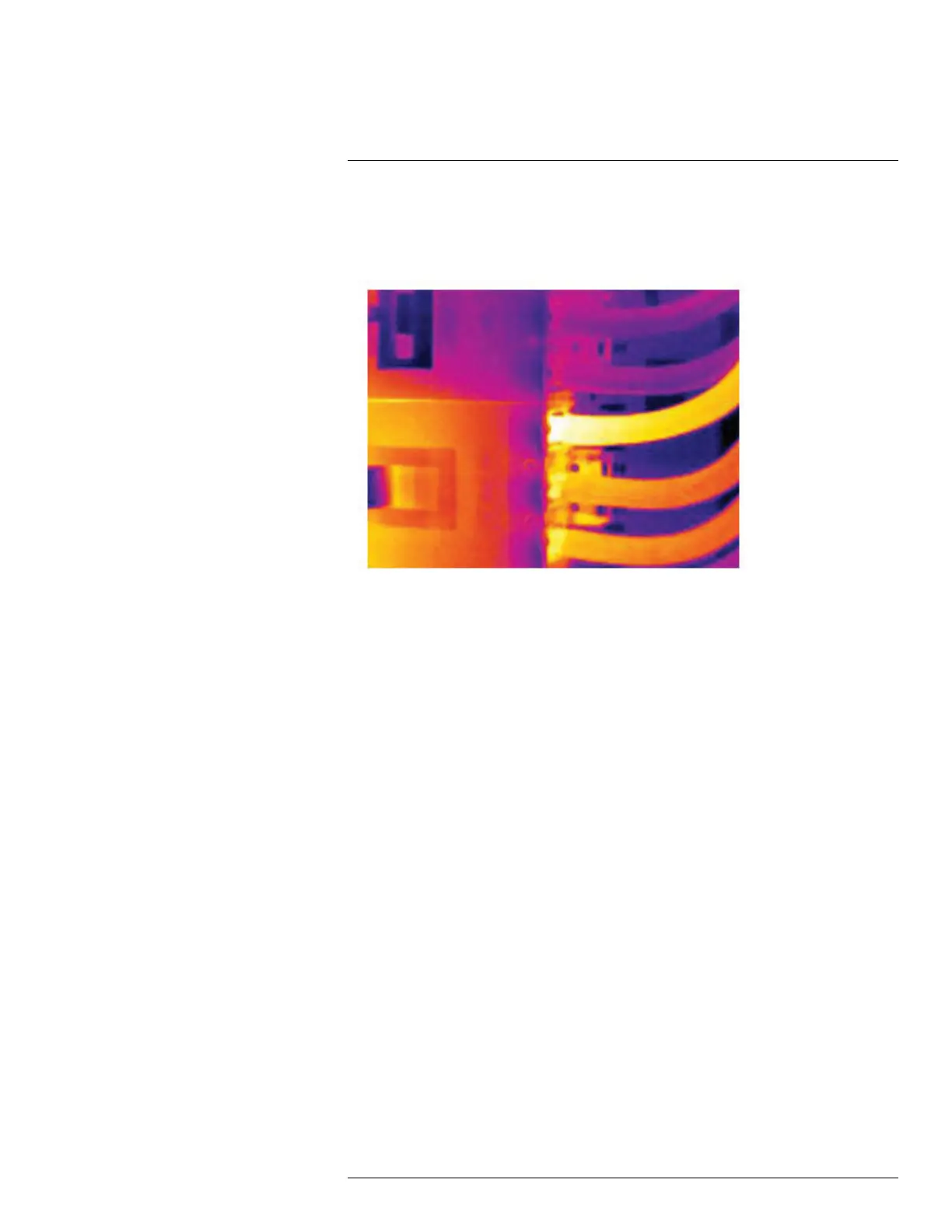
12.3.2 Figure
The image below shows a series of fuses where one fuse has a raised temperature on the
contact surfaces against the fuse holder. Because of the fuse holder’s blank metal, the
temperature increase is not visible there, while it is visible on the fuse’s ceramic material.
#T559918; r. AN/42281/42281; en-US
50