The measurement formula
19
2. Reflected emission from ambient sources = (1 – ε)τW
refl
, where (1 – ε) is the reflec-
tance of the object. The ambient sources have the temperature T
refl
.
It has here been assumed that the temperature T
refl
is the same for all emitting surfaces
within the halfsphere seen from a point on the object surface. This is of course some-
times a simplification of the true situation. It is, however, a necessary simplification in
order to derive a workable formula, and T
refl
can – at least theoretically – be given a val-
ue that represents an efficient temperature of a complex surrounding.
Note also that we have assumed that the emittance for the surroundings = 1. This is
correct in accordance with Kirchhoff’s law: All radiation impinging on the surrounding
surfaces will eventually be absorbed by the same surfaces. Thus the emittance = 1.
(Note though that the latest discussion requires the complete sphere around the object
to be considered.)
3. Emission from the atmosphere = (1 – τ)τW
atm
, where (1 – τ) is the emittance of the at-
mosphere. The temperature of the atmosphere is T
atm
.
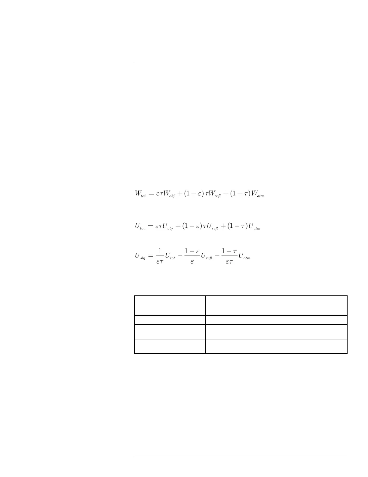
The total received radiation power can now be written (Equation 2):
We multiply each term by the constant C of Equation 1 and replace the CW products by
the corresponding U according to the same equation, and get (Equation 3):
Solve Equation 3 for U
obj
(Equation 4):
This is the general measurement formula used in all the FLIR Systems thermographic
equipment. The voltages of the formula are:
Table 19.1 Voltages
U
obj
Calculated camera output voltage for a blackbody of temperature T
obj
i.e. a voltage that can be directly converted into true requested object
temperature.
U
tot
Measured camera output voltage for the actual case.
U
refl
Theoretical camera output voltage for a blackbody of temperature
T
refl
according to the calibration.
U
atm
Theoretical camera output voltage for a blackbody of temperature
T
atm
according to the calibration.
The operator has to supply a number of parameter values for the calculation:
• the object emittance ε,
• the relative humidity,
• T
atm
• object distance (D
obj
)
• the (effective) temperature of the object surroundings, or the reflected ambient temper-
ature T
refl
, and
• the temperature of the atmosphere T
atm
This task could sometimes be a heavy burden for the operator since there are normally no
easy ways to find accurate values of emittance and atmospheric transmittance for the
#T559918; r. AN/42281/42281; en-US
79