EN-US English
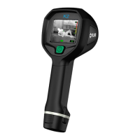
Camera parts
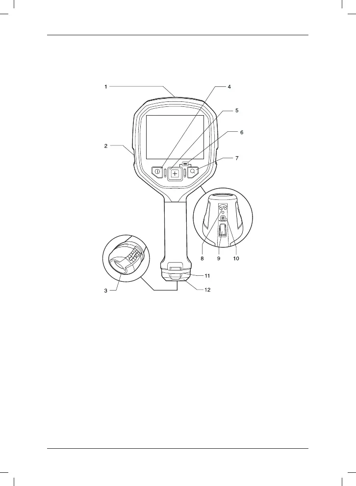
Figure
Explanation
1. USB Mini-B connector: Connect to a computer to download images using Flir
Tools.
2. Attachment point for lanyard strap/neck strap (left and right side).
3. Eccentric latch to secure the battery.
4. On/off button. This button has two functions:
• Push and holdto turn on/off.
• Push to go to default mode.
5. Mode button: Push repeatedly to select camera modes.
6. Access to setup menus and stored images: Push Mode + Zoom button.
7. Zoom button (zoom factor 2×).
8. Connectors for in-truck charger.
9. Save trigger. This trigger has two parallel functions:
• Pull the trigger: Save an image.
© 2013, Flir Systems, Inc. All rights reserved worldwide.
7
Publ. no. T559819, rev. A
 Loading...